Advertisement
18-GF07D1-2
ALL phases of this installation must comply with NATIONAL, STATE AND LOCAL CODES
Important: This Document is customer property and is to remain with this unit.
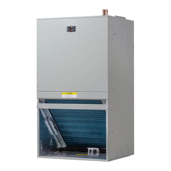
The TMM4A series wall mount air handler is designed for installation in a closet, utility room, alcove
and can be wall mounted. These versatile units are applicable to air conditioning applications. Field
installed electric resistance heaters are available.
Section 1. Features
1.1 Standard Features
FRONT OR BOTTOM RETURN AIR.
•
PAINTED FINISH ON GALVANIZED STEEL
•
STURDY POLYCARBONATE DRAIN PANS
•
- The TMM4A wall mount air handler has factory
installed drain pans and is shipped for upflow
applications only.
•
208/230 VAC OPERATION
STUD OR WALL MOUNTING TABS
•
FULLY INSULATED CABINET
•
3/4'' NPT PRIMARY AND SECONDARY DRAINS
•
1.2 Optional Accessories
5, 7.5 and 10 kW SINGLE PHASE ELECTRIC
•
HEATERS
- Circuit breakers are standard on all single
phase 5, 7.5 and 10 kW heaters.
Installer's Guide
WALL-MOUNT AIR HANDLERS
1.5-3TON COOLING/HEAT PUMP
(Limited heat pump combinations. See AHRI for details.)
TMM4A0A18S21SAA
TMM4A0A24S21SAA
TMM4A0B30S21SAA
TMM4A0B36S31SAA
Advertisement
Table of Contents

Subscribe to Our Youtube Channel
Related Manuals for American Standard TMM4A0A18S21SAA


Summary of Contents for American Standard TMM4A0A18S21SAA
- Page 1 18-GF07D1-2 Installer’s Guide WALL-MOUNT AIR HANDLERS 1.5-3TON COOLING/HEAT PUMP (Limited heat pump combinations. See AHRI for details.) TMM4A0A18S21SAA TMM4A0A24S21SAA TMM4A0B30S21SAA TMM4A0B36S31SAA ALL phases of this installation must comply with NATIONAL, STATE AND LOCAL CODES Important: This Document is customer property and is to remain with this unit.
-
Page 2: Section 2. Safety Information
Section 2. Safety Information Note: The small air handlers have been evaluated in accordance with the Code of Federal Regulations, Chapter XX, Part 3280 or the WARNING equivalent. “SUITABLE FOR MOBILE HOME USE.” SAFETY HAZARD! This information is intended for use by CAUTION individuals possessing adequate backgrounds of electrical and mechanical experience. -
Page 3: Section 3. Installation Instructions
Section 3. Installation Instructions WALL STRUTURE PROVIDED AIR HANDLER MOUNTING BRACKET 3.1 Unpacking Carefully unpack the unit and inspect the contents for damage. If any damage is found at the time of delivery, proper notification and claims should be made with the carrier. Check the rating plate to assure model number and voltage. -
Page 4: Condensate Drain
3.3 Duct Work Field ductwork must comply with the National Fire Protection Association NFPA 90A, NFPA 90B and any applicable local ordinance. AIRFLOW WARNING Do not, under any circumstances, connect return ductwork to any other heat producing device such as fireplace insert, stove, etc. Unauthorized use of such devices may result in fire, carbon monoxide poisoning, explosion, personal injury or property damage. -
Page 5: Power Wiring
3.5 Refrigerant Piping • Low voltage control connections are made to low voltage pigtails Refrigerant pipe connections are located on the top of the unit. extending from top of air handler (see Figure 1). Connections for Refrigerant piping external to the unit shall be sized in accordance control wiring are made with wire nuts. -
Page 6: Maintenance
3.11 Sequence of Operation Section 4. Wiring Cooling (cooling only) When the thermostat calls for cooling, the circuit from R to G is completed. The blower motor is energized directly by the 24VAC AC SYSTEMS signal from the thermostat. Outdoor Thermostat Air Handler The circuit from R to Y is also completed, energizing the compressor... - Page 7 Fig. 4-1...
- Page 8 Section 5. - Heater Pressure Drop Table - Use For All TMM4A Wall Mount Air Handler Models HE A TER R A CKS NUMBER OF R A CKS HE A TER MODEL N O . OF R A CKS AIRFL O W B A YHTRM505BRKAA MODEL AIR PRESSURE D R OP - INCHES W .G.
- Page 9 CFM(Watts) Model Motor External Static Pressure-Inches W.C.[kPa] Number Speed 0[0] 0.1[.02] 0.2[.05] 0.24[.06] 0.3[.07] 0.4[.10] 0.5[.12] 0.6[.15] 0.7[.17] 0.8[.20] Watts Amps 1.53 1.51 1.49 1.48 1.47 1.46 1.44 1187 1125 1076 1055 1021 Middle Watts Amps 1.67 1.66 1.64 1.63 1.62 1.61 1.59...
- Page 10 Section 7. Dimensional Data 6.1 UNIT DIMENSIONS Liquid line connection Low voltage copper (sweat)(3/8˝dia pipe) connection Vapor line connection copper (sweat)(3/4˝dia pipe) Breaker switch (for electric heater High voltage connection only) 7/8˝ dia knock outs Front return shown. Units may also be installed as bottom return.
- Page 11 16123000A06177 V1.1 6200 Troup Highway The manufacturer has a policy of continuous product and product Tyler, TX 75707 data improvement and reserves the right to change design and www.trane.com specifications without notice. www.americanstandardair.com © Trane U.S. Inc. 2013...
- Page 12 此页不做菲林,仅供说明 材料:双胶纸100克 尺寸:大A4 印刷颜色:黑白 版本由V1.0升级到V1.1 更改内容:客户要求更改第10页参数...
Need help?
Do you have a question about the TMM4A0A18S21SAA and is the answer not in the manual?
Questions and answers