
Summary of Contents for GE MDS MDS SD9
- Page 1 ™ MDS SD9 Software-Controlled Digital Communications Preliminary MDS 05-4659A01, Rev. 0 JULY 2008...
- Page 2 A power connector with screw-type retaining screws as supplied by GE MDS must be used. Do not disconnect equipment unless power has been switched off or the area is known to be non-hazardous.
-
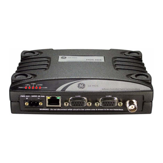
Page 3: Front Panel Connectors
INTRODUCTION This guide presents basic installation and operating instructions for the MDS SD9 Series wireless transceiver. The transceiver (Figure 1) is designed to operate in point-to-multi- point environments, including utility automation/distribution systems, and other telemetry functions. These radios are software-configurable to provide flexible operation in a variety of applications using one hardware platform. - Page 4 The contents of a shipment may have been modified to reflect customer-specific requirements given at the time of order. Additional accessories are available for our products. Contact your factory representative for assistance. MDS SD9 Startup Guide 05-xxxxA01, Rev. 01...
-
Page 5: Installation
• Correct data connections between the transceiver and the data device. Figure 3 shows a typical remote station arrangement. This is followed by step-by-step procedures for installing the transceiver and making front panel connections. 05-xxxxA01, Rev. 01 MDS SD9 Startup Guide... -
Page 6: Installation Steps
To prevent moisture from entering the radio, do not mount the NOTE: case with the cable connectors pointing up. Also, dress all cables to prevent moisture from running along the cables and into the radio. MDS SD9 Startup Guide 05-xxxxA01, Rev. 01... - Page 7 firmware. Refer to the Reference Manual for details. 4. Connect primary power to the transceiver. Power applied must be within 10.5–30 Vdc and capable of continuously providing at least 2.5 Amperes. A power connector with screw-terminals is pro- 05-xxxxA01, Rev. 01 MDS SD9 Startup Guide...
- Page 8 ENTER the ready “>” prompt on the screen. NOTE: To prevent unintended keying of the transmitter during , or do not management activities, set PTTSIG connect to Pin 6 of the port. COM1 MDS SD9 Startup Guide 05-xxxxA01, Rev. 01...
- Page 9 (typically xxxx xxxx ). The default setting is 4800 9600 9600 f. Set the radio’s serial data interface rate (typically BAUD 9600 This completes the initial setup and configuration of the radio. 05-xxxxA01, Rev. 01 MDS SD9 Startup Guide...
- Page 10 Signal-to-Noise Ratio (in dB). SPECTRUM Display internal spectrum analyzer, where [xxx.xx] xxx.xx characters denote center frequency in MHz. The command spectrum may be entered alone to view current operating channel. SREV Display the Software Revision Level. MDS SD9 Startup Guide 05-xxxxA01, Rev. 01...
-
Page 11: Troubleshooting
In addition to the top panel LEDs, the connector has ETHERNET/LAN two integrated LEDs. A steady green LED indicates that an Ethernet link has been established, a flashing green indicates data activity, and a yellow LED indicates 100 Mbps operation. 05-xxxxA01, Rev. 01 MDS SD9 Startup Guide... -
Page 12: Event Codes
NO ALARMS PRESENT If an alarm does exist, a two-digit alarm code (00–31) is displayed and the event is identified as a Major or Minor Alarm. A brief description of the alarm is also given. MDS SD9 Startup Guide 05-xxxxA01, Rev. 01... -
Page 13: Major Alarms Vs. Minor Alarms
The codes shown are a subset of a larger pool of codes used for various GE MDS products. For this reason, the table does not show a sequential listing of all code numbers. Only the codes appli- cable to this product are shown. - Page 14 PC to the radio for manage- COM1 ment or diagnostics. A straight-through cable is required that connects Pin 2 (RXD), Pin 3 (TXD), and Pin 5 (Ground). (See Figure MDS SD9 Startup Guide 05-xxxxA01, Rev. 01...
-
Page 15: Com2 Connections
Figure 9. COM2 Connector (DB-9F) As viewed from outside the radio Pin Descriptions—RS/EIA-232 Mode Table 5 lists the connector pin functions when configured to operate in RS/EIA-232 mode. For RS/EIA-422/485 mode, refer to the Reference Manual. 05-xxxxA01, Rev. 01 MDS SD9 Startup Guide... - Page 16 CTS delay time has elapsed (DCE), or keys an attached radio when RF data arrives (CTS KEY). Reserved—User I/O for special applications Additional information on Analog Mode operation (including NOTE: cable wiring details) is contained in the Reference Manual. MDS SD9 Startup Guide 05-xxxxA01, Rev. 01...
-
Page 17: Specifications
SPECIFICATIONS GENERAL Frequency Range*: MDS SD9: 920–960 MHz * Specific frequency authorizations are dependent on the type-approval of radio. Consult the factory for details. RECEIVER –6 Maximum Usable Sensitivity: –110 dBm at 1x10 BER (Preliminary) Bandwidth: 12.5, 25 kHz TRANSMITTER Carrier Power: 0.1 Watts to 5 Watts... -
Page 18: Diagnostics Interface
DIAGNOSTICS INTERFACE Signaling Standard: RS-232 (COM1) RS-232/RS-485 (COM2) Connector: COM1—DB-9F COM2—DB-9F Specifications are subject to change without notice or obligation. MDS SD9 Startup Guide 05-xxxxA01, Rev. 01... - Page 20 GE MDS, LLC 175 Science Parkway Rochester, NY 14620 General Business: +1 585 242-9600 FAX: +1 585 242-9620 Web: www.GEmds.com...