
Related Manuals for EWM MIRA 151


Summary of Contents for EWM MIRA 151
- Page 1 Operating instructions Welding machine Mira 151 KGE Mira 221 MV KGE Mira 251 KGE Mira 301 KGE - M1.02 099-005084-EW501 22.09.2011 Register now! For your benefit Jetzt Registrieren und Profitieren! www.ewm-group.com...
- Page 2 © EWM HIGHTEC WELDING GmbH · Dr. Günter-Henle-Str. 8 · D-56271 Mündersbach, Germany The copyright to this document remains the property of the manufacturer.
-
Page 3: Table Of Contents
5 Design and function..........................22 General ............................22 Installation............................ 23 Machine cooling ........................... 23 Workpiece lead, general ......................23 Mains connection ......................... 24 Mira 151 ............................24 5.6.1 Mira 221 MV ......................... 25 5.6.1.1 Connection with 230 V mains voltage............25 5.6.1.2 Connection with 400 V mains voltage............ - Page 4 Manufacturer's declaration to the end user ..............43 Meeting the requirements of RoHS....................43 7 Rectifying faults............................44 Customer checklist........................44 8 Technical data............................45 Mira 151, 221 MV, 251, 301......................45 9 Accessories ............................46 General accessories ........................46 10 Replaceable parts..........................47 10.1 Wire feed rollers ...........................47 10.1.1...
-
Page 5: Safety Instructions
Safety instructions Notes on the use of these operating instructions Safety instructions Notes on the use of these operating instructions DANGER Working or operating procedures which must be closely observed to prevent imminent serious and even fatal injuries. • Safety notes include the "DANGER" keyword in the heading with a general warning symbol. •... -
Page 6: Explanation Of Icons
Safety instructions Explanation of icons Explanation of icons Symbol Description Press Do not press Turn Switch Switch off machine Switch on machine ENTER (enter the menu) NAVIGATION (Navigating in the menu) EXIT (Exit the menu) Time display (example: wait 4s/press) Interruption in the menu display (other setting options possible) Tool not required/do not use Tool required/use... -
Page 7: General
Safety instructions General General DANGER Electromagnetic fields! The power source may cause electrical or electromagnetic fields to be produced which could affect the correct functioning of electronic equipment such as IT or CNC devices, telecommunication lines, power cables, signal lines and pacemakers. •... - Page 8 Safety instructions General WARNING Smoke and gases! Smoke and gases can lead to breathing difficulties and poisoning. In addition, solvent vapour (chlorinated hydrocarbon) may be converted into poisonous phosgene due to the ultraviolet radiation of the arc! • Ensure that there is sufficient fresh air! •...
- Page 9 Safety instructions General CAUTION Damage due to the use of non-genuine parts! The manufacturer's warranty becomes void if non-genuine parts are used! • Only use system components and options (power sources, welding torches, electrode holders, remote controls, spare parts and replacement parts, etc.) from our range of products! •...
- Page 10 Safety instructions General CAUTION EMC Machine Classification In accordance with IEC 60974-10, welding machines are grouped in two electromagnetic compatibility classes (see technical data): Class A machines are not intended for use in residential areas where the power supply comes from the low-voltage public mains network.
-
Page 11: Transport And Installation
Safety instructions Transport and installation Transport and installation WARNING Incorrect handling of shielding gas cylinders! Incorrect handling of shielding gas cylinders can result in serious and even fatal injury. • Observe the instructions from the gas manufacturer and in any relevant regulations concerning the use of compressed air! •... -
Page 12: Ambient Conditions
Safety instructions Ambient conditions Ambient conditions CAUTION Installation site! The machine must not be operated in the open air and must only be set up and operated on a suitable, stable and level base! • The operator must ensure that the ground is non-slip and level, and provide sufficient lighting for the place of work. -
Page 13: Intended Use
Intended use Applications Intended use WARNING Hazards due to improper usage! Hazards may arise for persons, animals and material objects if the equipment is not used correctly. No liability is accepted for any damages arising from improper usage! • The equipment must only be used in line with proper usage and by trained or expert staff! •... -
Page 14: Documents Which Also Apply
Intended use Documents which also apply Documents which also apply 3.3.1 Warranty NOTE For further information, please see the accompanying supplementary sheets "Machine and Company Data, Maintenance and Testing, Warranty"! 3.3.2 Declaration of Conformity The designated machine conforms to EC Directives and standards in terms of its design and construction: •... -
Page 15: Machine Description - Quick Overview
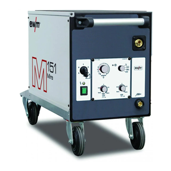
Machine description – quick overview Front view Machine description – quick overview Front view Figure 4-1 Item Symbol Description Carrying handle Machine control See Machine control – operating elements chapter Wheels, guide castors Connection socket, workpiece lead Central connection for welding torch (Euro) Integrated welding current, shielding gas and torch trigger 099-005084-EW501 22.09.2011... -
Page 16: Rear View
Machine description – quick overview Rear view Rear view Figure 4-2 Item Symbol Description Securing elements for shielding gas cylinder (strap/chain) Key button, Automatic cutout Wire feed motor supply voltage fuse (press to reset a triggered fuse) Connecting nipple G¼, shielding gas connection Bracket for shielding gas cylinder Wheels, fixed castors Mains connection cable... -
Page 17: Inside View
Machine description – quick overview Rear view 4.2.1 Inside view Figure 4-3 Item Symbol Description Inspection window for checking the wire and handle for opening the cover Wire delivery unit cover Wire feed unit Wire inching button Wire spool holder Flap support 099-005084-EW501 22.09.2011... -
Page 18: Machine Control - Operating Elements
Machine description – quick overview Machine control – Operating elements Machine control – Operating elements 4.3.1 Mira 151 Figure 4-4 Item Symbol Description Step switch, welding voltage Signal light, Functional error On when excess temperature detected Main switch, machine on/off Rotary dial, Spot and interval times Infinite adjustment of the welding time (0-20s) in "Spots and interval"... -
Page 19: Mira 221 Mv
Machine description – quick overview Machine control – Operating elements 4.3.2 Mira 221 MV Figure 4-5 Item Symbol Description Step switch, welding voltage Signal light, Functional error On when excess temperature detected Main switch, alternate 230V/Off/400V 230 V 40 0V 230V position Machine switched on (with 1 x 230V mains connection) Position 0... -
Page 20: Mira 251
Machine description – quick overview Machine control – Operating elements 4.3.3 Mira 251 Figure 4-6 Item Symbol Description Step switch, welding voltage Signal light, Functional error On when excess temperature detected Main switch, machine on/off Rotary dial, Spot and interval times Infinite adjustment of the welding time (0-20s) in "Spots and interval"... -
Page 21: Mira 301
Machine description – quick overview Machine control – Operating elements 4.3.4 Mira 301 Figure 4-7 Item Symbol Description Step switch, welding voltage Signal light, Functional error On when excess temperature detected Main switch, machine on/off Rotary dial, Spot and interval times Infinite adjustment of the welding time (0-20s) in "Spots and interval"... -
Page 22: Design And Function
Design and function General Design and function General WARNING Risk of injury from electric shock! Contact with live parts, e.g. welding current sockets, is potentially fatal! • Follow safety instructions on the opening pages of the operating instructions. • Commissioning may only be carried out by persons who have the relevant expertise of working with arc welding machines! •... -
Page 23: Installation
Design and function Installation CAUTION Damage due to incorrect connection! Accessory components and the power source itself can be damaged by incorrect connection! • Only insert and lock accessory components into the relevant connection socket when the machine is switched off. •... -
Page 24: Mains Connection
Before connecting to the mains network and before disconnecting from the mains network: • Move the mains switch to the "0" position Mira 151 NOTE The machine may be connected and operated on all TN or TT networks with a neutral conductor and a protective conductor. -
Page 25: Mira 221 Mv
Design and function Mira 151 5.6.1 Mira 221 MV 5.6.1.1 Connection with 230 V mains voltage NOTE Use the "CEE16/SHOCK-PROOF" adapter provided to connect to the 230V mains power. The machine may be connected and operated on all TN or TT networks with a neutral conductor and a protective conductor. -
Page 26: Connection With 400 V Mains Voltage
Design and function Mira 151 5.6.1.2 Connection with 400 V mains voltage NOTE The machine may be connected to TN, TT or IT networks with a protective conductor (as available). Figure 5-3 Legend Item Designation Colour code Outer conductor 1... -
Page 27: Mira 251, 301
Design and function Mira 151 5.6.2 Mira 251, 301 NOTE The machine may be connected to TN, TT or IT networks with a protective conductor (as available). Figure 5-4 Legend Item Designation Colour code Outer conductor 1 black Outer conductor 2... -
Page 28: Welding Torch And Workpiece Line Connection
Design and function Welding torch and workpiece line connection Welding torch and workpiece line connection Depending on the wire electrode diameter or type, either a spiral guide or plastic core with the correct inner diameter has to be inserted in the torch! Recommendation: •... - Page 29 Design and function Welding torch and workpiece line connection Figure 5-5 Item Symbol Description Central connection for welding torch (Euro) Integrated welding current, shielding gas and torch trigger Welding torch hose package Welding torch Connection socket, workpiece lead Workpiece lead Workpiece •...
-
Page 30: Shielding Gas Supply
Design and function Shielding gas supply Shielding gas supply WARNING Risk of accident by exceeding the maximum size of the gas cylinder! Maximum permissible shielding gas cylinder size at fill pressure. Exceeding these limits can cause the loss of steadiness up to an angle of 10° (IEC 60974-2). This can cause injuries. -
Page 31: Connecting The Shielding Gas Supply
Design and function Shielding gas supply 5.8.1 Connecting the shielding gas supply Figure 5-6 Item Symbol Description Securing elements for shielding gas cylinder (strap/chain) Bracket for shielding gas cylinder Connecting nipple G¼, shielding gas connection • Place the shielding gas cylinder into the relevant cylinder bracket. •... -
Page 32: Setting The Shielding Gas Quantity
Design and function Shielding gas supply Figure 5-7 Item Symbol Description Pressure regulator Shielding gas cylinder Output side of the pressure regulator Cylinder valve • Tighten the pressure regulator screw connection on the gas bottle valve to be gas-tight. • Screw gas hose connection crown nut onto the output side of the pressure regulator. -
Page 33: Inserting The Wire Electrode
Design and function Inserting the wire electrode Inserting the wire electrode 5.9.1 Inserting the wire spool NOTE Standard D300 wire spool holder can be used. Adapters (see accessories) are required when using standardised basket coils (DIN 8559). Figure 5-8 Item Symbol Description Carrier pin For fixing the wire spool... -
Page 34: Changing The Wire Feed Rollers
Design and function Inserting the wire electrode 5.9.2 Changing the wire feed rollers NOTE Unsatisfactory welding results due to faulty wire feeding! Wire feed rollers must be suitable for the diameter of the wire and the material. • Check the roller label to verify that the rollers are suitable for the wire diameter. Turn or change if necessary! •... -
Page 35: Inching The Wire Electrode
Design and function Inserting the wire electrode NOTE The welding wire is fed into the rear groove on the wire roll! • Labels relate to the rear groove on the wire roll when installed. Figure 5-10 5.9.3 Inching the wire electrode CAUTION Risk of injury due to moving parts! The wire feed units are equipped with moving parts, which can trap hands, hair,... - Page 36 Design and function Inserting the wire electrode Figure 5-11 Item Symbol Description Pressure units Clamping units Wire feed nipple Capillary tube or plastic core with support tube, depending on the torch equipment • Extend and lay out the torch tube package. •...
-
Page 37: Spool Brake Setting
Design and function Inserting the wire electrode 5.9.4 Spool brake setting Figure 5-12 Item Symbol Description Allen screw Securing the wire spool retainer and adjustment of the spool brake • Tighten the Allen screw (8 mm) in the clockwise direction to increase the braking effect. NOTE Tighten the spool brake until the wire spool no longer turns when the wire feed motor stops but without it jamming during operation! -
Page 38: Mig/Mag Operating Point
Design and function MIG/MAG functional sequences / operating modes 5.9.5 MIG/MAG operating point Operating Action Result element Select operating mode non-latched latched spots or interval Wire speed setting m /m in Welding voltage setting NOTE It is not necessary to set other parameters. The permanently set gas pre-flow time is 200ms. -
Page 39: Non-Latched Operation
Design and function MIG/MAG functional sequences / operating modes 5.10.2 Non-latched operation Figure 5-13 1st cycle • Press and hold torch trigger. • Shielding gas is expelled (gas pre-flows). • Arc ignites after the wire electrode makes contact with the workpiece. •... -
Page 40: Spot Welding
Design and function MIG/MAG functional sequences / operating modes 5.10.4 Spot welding Figure 5-15 Start • Press and hold torch trigger. • Shielding gas is expelled (gas pre-flows). • Arc ignites after the wire electrode makes contact with the workpiece. •... -
Page 41: Interval
Design and function MIG/MAG functional sequences / operating modes 5.10.5 Interval Figure 5-16 Start • Press and hold torch trigger. • Shielding gas is expelled (gas pre-flows). • Arc ignites after the wire electrode makes contact with the workpiece. • Welding current flows. -
Page 42: Maintenance, Care And Disposal
Maintenance, care and disposal General Maintenance, care and disposal DANGER Risk of injury from electric shock! Cleaning machines that are not disconnected from the mains can lead to serious injuries! • Disconnect the machine completely from the mains. • Remove the mains plug! •... -
Page 43: Maintenance Work
Information about giving back used equipment or about collections can be obtained from the respective municipal administration office. • EWM participates in an approved waste disposal and recycling system and is registered in the Used Electrical Equipment Register (EAR) under number WEEE DE 57686922. •... -
Page 44: Rectifying Faults
Rectifying faults Customer checklist Rectifying faults All products are subject to rigorous production checks and final checks. If, despite this, something fails to work at any time, please check the product using the following flowchart. If none of the fault rectification procedures described leads to the correct functioning of the product, please inform your authorised dealer. -
Page 45: Technical Data
Technical data Mira 151, 221 MV, 251, 301 Technical data Mira 151, 221 MV, 251, 301 NOTE Performance specifications and guarantee only in connection with original spare and replacement parts! Mira 221 MV Switching steps Welding current setting 30 A–150 A 30 A–220 A... -
Page 46: Accessories
Accessories General accessories Accessories General accessories Type Designation Item no. ADAP DZA/EZA Adapter for welding torches with Dinse connector to 094-016765-00000 Euro central connector, on the machine AK300 Adapter for K300 basket coil 094-001803-00001 DM1 32L/MIN Manometer pressure regulator 094-000009-00000 GH 2X1/4'' 2M Gas hose 094-000010-00001... -
Page 47: Replaceable Parts
Replaceable parts Wire feed rollers Replaceable parts CAUTION Damage due to the use of non-genuine parts! The manufacturer's warranty becomes void if non-genuine parts are used! • Only use system components and options (power sources, welding torches, electrode holders, remote controls, spare parts and replacement parts, etc.) from our range of products! •... -
Page 48: 4-Roll Drive
Replaceable parts Wire feed rollers 10.1.2 4-roll drive 10.1.2.1 Wire feed roller for steel wires Type Designation Item no. FE 2DR4R 0,6+0,8 Drive rollers, 37 mm, steel 092-000839-00000 FE 2DR4R 0,8+1,0 Drive rollers, 37 mm, steel 092-000840-00000 FE 2DR4R 0,9+1,2 Drive rollers, 37 mm, steel 092-000841-00000 FE 2DR4R 1,0+1,2... -
Page 49: Overview Of Ewm Branches
Appendix A Overview of EWM branches Appendix A 11.1 Overview of EWM branches 099-005084-EW501 22.09.2011...
Need help?
Do you have a question about the MIRA 151 and is the answer not in the manual?
Questions and answers