
Summary of Contents for E-Tech IP-100
-
Page 1: Table Of Contents
E-TECH Co., Ltd 1/19 ▶ Table of Contents◀ 1. Introduction 2. Description of Unit 3. Technical Specifications 4. Theory of Operation 5. Circuit Descriptions 6. Alignment Procedure FILE: IP 100 service manual.doc 2004.05.01... -
Page 4: Introduction
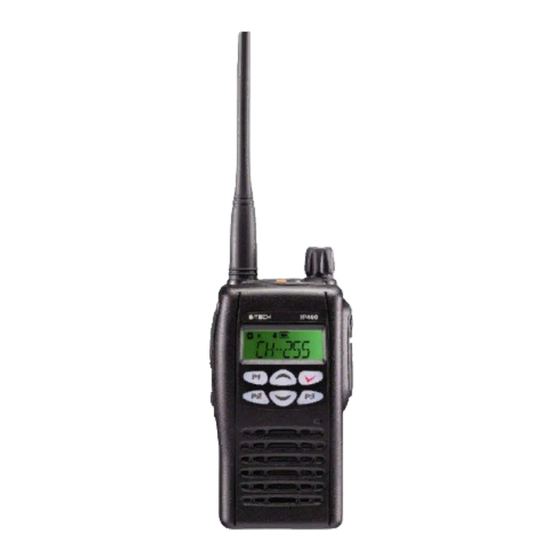
E-TECH Co., Ltd 2/19 1. Introduction IP-100 has a compact size with a various features in the range of 136~174MHz. IP-100 Has a various features shown as below. IP-100 constructed with a microprocessor controlled, temperature compensated Phase Locked Loop(PLL) frequency synthesizer. The radio features a double conversion receiver and a direct FM transmitter modulator. -
Page 5: Technical Specifications
E-TECH Co., Ltd 3/19 3. Technical Specifications 3-1 General 1) Frequency range 136~174 MHz 2) Channels 255 Channels 3) Channel spacing 12.5 kHz/25 kHz 4) Communication method : Simplex 5) Antenna Impedance 50 ohm 6) Antenna Helical Antenna 7) Power supply voltage LI-1700mAh Li-Ion battery pack(Voltage: 7.5V DC) -
Page 6: Theory Of Operation
E-TECH Co., Ltd 4/19 3-3 Receiver 1) Receiver Type Double Super Hetero type -0.25uV 이하(12dB SINAD 시) 2) Sensitivity 3) Frequency Stability ±0.00025%(±2.5PPM) 4) SPURIOUS Rejection -60 dB 5) Adjacent Channel Selectivity: -60 dB (Narrow) , -70 dB (Wide) 6) Distortion 5% (1 kHz 60%) ~... - Page 7 E-TECH Co., Ltd 5/19 4-1 Features & Operation 1. Monitor Press the Monitor key momentarily to disable the Tone squelch. 2. Radio Call By using Various 5Tone, individual / Group call is available. 16 Receiving codes are available as well as open call.
- Page 8 E-TECH Co., Ltd 6/19 4-2 LCD Display and Icons 1.ANT GAZE ; Shows the received signal strength. 2.TX POWER HIGH: Indicate power level 3.KEY LOCK: Appears during key lock function is ON. 4.ALART(BEEP) ON/OFF: Appears when beep sound is turned ON.
- Page 9 E-TECH Co., Ltd 7/19 3. Contact list to enter Menu Mode. to until to select to scroll list to exit 4. Status call list 4-1. Making STATUS call to enter Menu Mode. to until to select to scroll list 5) Push PTT KEY for sending message on the LCD.
- Page 10 E-TECH Co., Ltd 8/19 5. Lone work to enter Menu Mode. to until to select to select ON/OFF 6. Tx power to enter Menu Mode. to until to select to select HIGH / LOW POWER to select 7. Tx Tone Selecting Transmitting TONE(CTCSS/DCS).
- Page 11 E-TECH Co., Ltd 9/19 8. Rx Tone Changing Receiving TONE(CTCSS/DCS). to enter Menu Mode. to until to select to select TONE either CTCSS or DCS. 0= NON TONE 1-38 CTCSS 101 – 183 DCS TONE. to select exit 9. Group Changing GROUP Tone.
- Page 12 E-TECH Co., Ltd 10/19 11. Key lock to enter Menu Mode. to until to select to select key lock /unlock. to select 12. Squelch level 16 level is available. 0 = terminate sq function to enter Menu Mode. to until...
- Page 13 E-TECH Co., Ltd 11/19 4) Push PTT for exit 15. DTMF to enter Menu Mode. to until to select to select ON /OFF. to select 16. Vox on/off to enter Menu Mode. to until to select to select ON /OFF.
- Page 14 E-TECH Co., Ltd 12/19 18. Auto Vox to enter Menu Mode. to until to select to select ON /OFF. to select 19. Priority Scan to enter Menu Mode. to until to select to select ON /OFF. to select 20. Priority scan CH to enter Menu Mode.
- Page 15 E-TECH Co., Ltd 13/19 21. Power save to enter Menu Mode. to until to select to select ON /OFF. to select 22. Talkaround to enter Menu Mode. to until to select to select ON /OFF. to select 23. Password to enter Menu Mode.
- Page 16 E-TECH Co., Ltd 14/19 24. Password CH to enter Menu Mode. to until to select 4) ---- will display on the LCD( enter old password) by pushing up and down KEY to change password. by pushing enter KEY to change digit of password.
-
Page 17: Circuit Descriptions
E-TECH Co., Ltd 15/19 27. Status call Send to enter Menu Mode. to until to select to select ON /OFF. to select 5. Circuit Description. 5-1 Transmitter 1) MIC AMP Circuit Voice signal from the microphone are applied to microphone amplifier U303. U303 contains a low-pass filter that has a 6dB/oct response between 300Hz and 3kHz and eliminate above 3kHz. - Page 18 E-TECH Co., Ltd 16/19 4) IF Circuit The first signals from Q102 are fed to the matched pair crystal filter FL101, then IF signals are amplified in Q103. And those signals are fed to U101 which is composed of the second local oscillator, second local oscillator, second mixer, limiter amplifier, quadrature detector and active filter circuit.
- Page 19 E-TECH Co., Ltd 17/19 Alignment 6-1 Alignment point FILE: IP 100 Service manual.doc 2004.05.01...
- Page 20 E-TECH Co., Ltd 18/19 6-2 Voltage Check 1) Set up the radio frequency to (136.025[Mhz]) then measure whether R/Tx voltage is over 0.8[v]. 2) Set up the radio frequency (173.975[Mhz]) then measure whether R/Tx voltage is under 5[v]. 3) When Un-Lock is display on LCD means defective goods.
Need help?
Do you have a question about the IP-100 and is the answer not in the manual?
Questions and answers