Table of Contents
Advertisement
Quick Links
Advertisement
Table of Contents

Subscribe to Our Youtube Channel
Related Manuals for Aluratek CDM530AM


Summary of Contents for Aluratek CDM530AM
- Page 1 WiFi Mobile Broadband Gateway User Manual...
-
Page 2: Fcc Interference Statement
Copyright The contents of this publication may not be reproduced in any part or as a whole, stored, transcribed in an information retrieval system, translated into any language, or transmitted in any form or by any means, mechanical, magnetic, electronic, optical, photocopying, manual, or otherwise, without the prior written permission. -
Page 3: Table Of Contents
Table of Contents FCC Interference Statement................2 Introduction....................4 1.1. Package Contents .................4 1.2. System Requirements for Configuration........5 1.3. Interfaces ..................5 The Rear View ....................5 The Top View....................6 1.4. LEDs– the Front View..............7 1.5. Features ..................9 Configuring Wireless WAN Mobile broadband Router ......10 2.1. -
Page 4: Introduction
1. Introduction The WiFi Mobile Broadband Gateway is a high-performance tool that supports wireless networking at home, work, or in a public place. The WiFi Mobile Broadband Gateway supports uses a USB 3G modem card, either WCDMA or EVDO and even HSDPA as well, and supports wireless data transfers up to 80M bps, and wired data transfers up to 100 Mbps. -
Page 5: System Requirements For Configuration
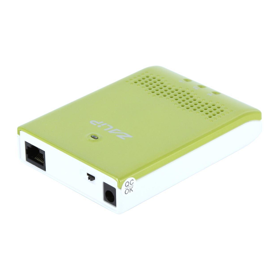
Using a power supply with a different voltage rating than the one included Caution: with the WiFi Mobile Broadband Gateway will cause damage and void the warranty for this product. 1.2. System Requirements for Configuration • A compatible USB 3G modem card with service Note: Subject to services and service terms available from your carrier. - Page 6 The Side View USB port for connecting Reset Button WPS Button with 3G USB modem Restore to Original factory WiFi Network security defaulted setting setup NOTE: Press the reset button 3 seconds: the LEDs (WiFi and USB) will flash 2 times, and Ethernet port be resented to LAN.
-
Page 7: The Top View
1.4. LEDs– The Top View Power LED (Battery Status) WiFi LED Ethernet LED USB LED A green light as A green light as (3G Status) connection on WAN is connected A green light as WLAN available power is on and Power LED: (and Battery Status) when device is on and with battery inside Green: power adapter is plugged, and battery is fully charged... - Page 8 Green in flash: data packet transferred via Ethernet USB LED: (WAN) Green: 3G/3.5G connection is established Green in flash: data packet transferred via 3G/3.5G connection WiFi LED: Green: WLAN is active and available Green in flash: data packet transferred via WLAN...
-
Page 9: Features
1.5. Features „ IEEE 802.11b/g/n compliant ¾ Backward compatible to IEEE 802.11b standards ¾ Max physical rate up to 54Mbps in 802.11g mode ¾ Security Supports: WEP (64/128 bits), WPA, WPA2, WPA-PSK, WPA2-PSK, and 802.1x „ Provide 1 * 10/100 RJ-45 port ¾... -
Page 10: Configuring Wireless Wan Mobile Broadband Router
2. Configuring Wireless WAN Mobile broadband Router 2.1. Installation Considerations The WiFi Mobile Broadband Gateway allows you access your network using a wireless connection, from virtually anywhere within its operating range. Keep in mind however, that the number, thickness, and location of walls, ceilings, or other objects that the wireless signals must pass through, may limit this range. - Page 11 a. Insert the battery into battery holder 3. Connect a USB modem with service to the WiFi Mobile Broadband Gateway in one of the following ways: Æ You can plug your USB modem into the USB interface. ---see Picture 2.2 Picture 2.2 Note: The WiFi Mobile Broadband Gateway is designed to work with...
- Page 12 Picture 2.3 The WiFi Mobile Broadband Gateway Ethernet Port is “Auto-MDI/MDIX.” Note: This provides patch Ethernet cable Ethernet Port access. 4. Connect the power adapter to the receptor on the back panel of your WiFi Mobile Broadband Gateway. Then plug the other end of the power adapter into a wall outlet or power strip.
-
Page 13: Establish Wifi Connection
6. The LEDs (See Picture 2.5) a. The Power LED will turn ON to indicate power has been applied. b. Reference the Section 1.4, LEDs– the Top View. Picture 2.5 2.1.2. Establish WiFi Connection If you selected either encryption, ensure these settings WPA-PSK match your WiFi adapter settings. -
Page 14: Using The Configuration Menu
3. Using the Configuration M Once properly configured, the WiFi Mobile Broadband Gateway will obtain and assign IP address information automatically. Configuration settings can be established through the WiFi Mobile Broadband Gateway Configuration Menu. You can access this interface by performing the steps listed below: 1. - Page 15 3. Type “ in the field. admin” Password 4. Click “login” button.
-
Page 16: Wizard Setting
3.1. Wizard setting Press “Wizard” button Æ for basic settings with simpler way. (Please check section 3.1) Or you may click on “Advanced Setup” Æ for advanced settings. (Please check the section Administrator’s Main Menu. Each item from section 3.2) Click on “Enter”... - Page 17 Step 1: Allow you to change the system password. You can change Password here. It is recommended that you change the system password into the one you prefer to on the basis of security. 1. Key in your Old Password (if it is the first initiation, the “admin” will be the defaulted one. 2: Enter your New Password...
- Page 18 3: Enter your Password again for confirmation; it must be the same as the New Password. Then on “Next” to get into next installation. click Step 2: Allow you to change the Time Zone. You can change Time Zone here. Or you can click the button “Detect Again”, the Time Zone will be changed to same with your...
- Page 19 Step : Select WAN Types will be used for Internet connection The Ethernet Port will be set as WAN port, if you select the Dynamic, Static, PPPOE, PPTP or L2TP WAN Types. The Ethernet Port will be set as LAN port, if you select the 3G WAN Type. Pick up one of types you preferred to.
- Page 20 Step 4: Configure the LAN IP Address, Host Name and WAN MAC Address. LAN is short for Local Area Network, and is considered your internal network. These are the IP settings of the LAN interface for the WiFi Mobile Broadband Gateway, and they may be referred to as Private settings.
- Page 21 Step 5: Configure the wireless settings. 1. Select “ ” or “ ”. The default setting is “ ”. Enable Disable Enable 2. Network ID( SSID) will be defaulted. Select Wireless Channel matching to your local area for Wireless ChannelÆ connection.
- Page 22 Step 6: Select the Wireless security method of your wireless configuration. Click on “Next” to continue.
- Page 23 Step 7: Summary 1. Select the option box “The Ethernet Port will be set as WAN Port after saving, confirm?” or “The Ethernet Port will be set as LAN Port after saving, confirm?” for continues. 2. Click on the “Apply Settings” button.
- Page 24 Step 8: System is applying. Click “Finish” button to back the Status Page.
-
Page 25: Administrator's Main Menu
3.2. Administrator’s Main Menu 3.2.1 Basic Setting... - Page 26 3.2.1.1 Primary Setup Ethernet port Configuration: Off: Disable the Ethernet port. LAN: The Ethernet port is as LAN port. WAN: The Ethernet port is as LAN port. Auto: It will be WAN Port if detect a DHCP server on the Ethernet port. Otherwise will be LAN port.
- Page 27 4.2 Dynamic IP Address: 1. Host Name: optional, required by some ISPs, for example, @Home. 2. Connection Control: There are 3 modes to select: Connect-on-demand: The device will link up with ISP when the clients send...
- Page 28 outgoing packets. Auto Reconnect Always-on): The device will link with ISP until the connection is established. Manually: The device will not make the link until someone clicks the connect-button in the Status-page. 4.3 PPP over Ethernet 1. PPPoE Account and Password: the account and password your ISP assigned to you.
- Page 29 4.4 PPTP First, please check your ISP assigned and Select Static IP Address or Dynamic IP Address. For example: Use Static, the private IP address, subnet mask and Gateway are your ISP assigned to you. 1. My IP Address and My Subnet Mask: the private IP address and subnet mask your ISP assigned to you.
- Page 30 default MTU value is 0(auto). 4.5 L2TP First, please check your ISP assigned and Select Static IP Address or Dynamic IP Address. For example: Use Static, the private IP address, subnet mask and Gateway are your ISP assigned to you. 1.
- Page 31 4.6 3G For 3G WAN Networking. The WAN fields may not be necessary for your connection. The information on this page will only be used when your service provider requires you to enter a User Name and Password to connect to the 3G network. Please refer to your documentation or service provider for additional information.
- Page 32 established. Manually: The device will not make the link until someone clicks the connect-button in the Status-page. Connection will be broken when the idle time arrives. 10. Maximum Idle Time: The 11. Maximum Transmission Unit (MTU): Most ISP offers MTU value to users. The default MTU value is 0(auto).
- Page 33 3.2.1.2 DHCP Server Press “More>>”, 1. DHCP Server: Choose either Disable or Enable 2. Lease Time: DHCP lease time to the DHCP client 3. IP Pool Starting/Ending Address: Whenever there is a request, the DHCP server will automatically allocate an unused IP address from the IP address pool to the requesting computer.
- Page 34 DHCP Clients List The list of DHCP clients shows here. DHCP Fixed Mapping The DHCP Server will reserve the special IP for special MAC address, shows below.
- Page 35 3.2.1.3 Wireless Settings Wireless settings allow you to set the wireless configuration items. is the Selecting this option will allow you to set your Wireless: Enabled default. Wireless Access Point (WAP) settings. Choose AP mode or Client mode. The factory default Wireless Operation Mode: setting is AP mode.
- Page 36 Open Open system authentication simply consists of two communications. The first is an authentication request by the client that contains the station ID (typically the MAC address). This is followed by an authentication response from the AP/router containing a success or failure message. An example of when a failure may occur is if the client's MAC address is explicitly excluded in the AP/router configuration.
- Page 37 WPS (Wi-Fi Protection Setup) WPS is Wi-Fi Protection Setup which is similar to WCN-NET and offers safe and easy way in Wireless Connection. The Config Method, we are support the PIN Code only. Wireless Client List The list of wireless client is shows here.
- Page 38 3.2.1.4 Change Password You can change Password here. We strongly recommend you to change the system password for security reason. Click on “Save” to store what you just select or “Undo” to give up...
- Page 39 3.2.2 Forwarding Rules...
- Page 40 3.2.2.1 Virtual Server This product’s NAT firewall filters out unrecognized packets to protect your Intranet, so all hosts behind this product are invisible to the outside world. If you wish, you can make some of them accessible by enabling the Virtual Server Mapping. A virtual server is defined as a Service Port, and all requests to this port will be redirected to the computer specified by the Server IP.
- Page 41 3.2.2.2 Special AP Some applications require multiple connections, like Internet games, Video conferencing, Internet telephony, etc. Because of the firewall function, these applications cannot work with a pure NAT router. The Special Applications feature allows some of these applications to work with this product. If the mechanism of Special Applications fails to make an application work, try setting your computer as the DMZ host instead.
- Page 42 3.2.2.3 Miscellaneous 1. IP Address of DMZ Host DMZ (Demilitarized Zone) Host is a host without the protection of firewall. It allows a computer to be exposed to unrestricted 2-way communication for Internet games, Video conferencing, Internet telephony and other special applications. 2.
- Page 43 3.2.3 Security Setting...
- Page 44 3.2.3.1 Packet Filters Packet Filter includes both outbound filter and inbound filter. And they have same way to setting. Packet Filter enables you to control what packets are allowed to pass the router. Outbound filter applies on all outbound packets. However, inbound filter applies on packets that destined to Virtual Servers or DMZ host only.
- Page 45 Each rule can be enabled or disabled individually. Click on “Save” to store what you just select or “Undo” to give up...
- Page 46 3.2.3.2 Domain Filters 1. Domain Filter Let you prevent users under this device from accessing specific URLs. 2. Domain Filter Enable Check if you want to enable Domain Filter. 3. Log DNS Query Check if you want to log the action when someone accesses the specific URLs. 4.
- Page 47 URL Blocking URL Blocking will block LAN computers to connect to pre-define Websites. The major difference between “Domain filter” and “URL Blocking” is Domain filter require user to input suffix (like .com or .org, etc), while URL Blocking require user to input a keyword only. In other words, Domain filter can block specific website, while URL Blocking can block hundreds of websites by simply a keyword.
- Page 48 3.2.3.3 MAC Control MAC Address Control allows you to assign different access right for different users and to assign a specific IP address to a certain MAC address. 1. MAC Address Control Check “Enable” to enable the “MAC Address Control”. All of the settings in this page will take effect only when “Enable”...
- Page 49 3.2.3.4 Miscellaneous 1. Administrator Time-out The time of no activity to logout automatically, you may set it to zero to disable this feature. 2. Remote Administrator Host/Port In general, only Intranet user can browse the built-in web pages to perform administration task.
- Page 50 3.2.3.5 Advanced Setting...
- Page 51 3.2.3.6 System Log This page support two methods to export system logs to specific destination by means of syslog (UDP) and SMTP(TCP). The items you have to setup including: 1. IP Address for Sys log Host IP of destination where sys log will be sent to. Check Enable to enable this function.
- Page 52 3.2.3.7 Dynamic DNS To host your server on a changing IP address, you have to use dynamic domain name service (DDNS). So that anyone wishing to reach your host only needs to know the name of it. Dynamic DNS will map the name of your host to your current IP address, which changes each time you connect your Internet service provider.
- Page 53 3.2.3.8 Provide different priority to different users or data flows, or guarantee a certain level of performance. 1. Enable This Item enables QoS function or not. 2. Bandwidth of Upstream Set the limitation of upstream speed. 3. Local: IP Define the Local IP address of packets here. 4.
- Page 54 4.7.7 schedule. Click on “Save” to store what you just select or “Undo” to give up...
- Page 55 3.2.3.9 SNMP In brief, SNMP, the Simple Network Management Protocol, is a protocol designed to give a user the capability to remotely manage a computer network by polling and setting terminal values and monitoring network events. 1. Enable SNMP You must check Local, Remote or both to enable SNMP function. If Local is checked, this device will response request from LAN.
- Page 56 3.2.3.10 Routing 1. Routing Tables Allow you to determine which physical interface address to use for outgoing IP data grams. If you have more than one routers and subnets, you will need to enable routing table to allow packets to find proper routing path and allow different subnets to communicate with each other.
- Page 57 3.2.3.11 System Time 1. Time Zone Select a time zone where this device locates. 2. Auto-Synchronization Select the “Enable” item to enable this function. 3. Time Server Select a NTP time server to consult UTC time 4. Sync with Time Server Select if you want to set Date and Time by NTP Protocol.
- Page 58 3.2.3.12 Scheduling You can set the schedule time to decide which service will be turned on or off. Select the “Enable” item. Press “Add New Rule” You can write a rule name and set which day and what time to schedule from “Start Time” to “End Time”. The following example configure “ftp time” as everyday 14:10 to 16:20...
- Page 59 Click on “Save” to store what you just select.
- Page 60 3.2.4 Tool Box...
- Page 61 3.2.4.1 System Info You can view the System Information and System log. And download/clear the System log, in this page.
- Page 62 3.2.4.2 Firmware Upgrade You can upgrade firmware by clicking “Upgrade” button. 3.2.4.3 Backup Setting You can backup your settings by clicking the “Backup Setting” button and save it as a bin file. Once you want to restore these settings, please reference the Section 3.2.5.2 Firmware Upgrade.
-
Page 63: Troubleshooting
Troubleshooting This section provides an overview of common issues, and possible solutions for the installation and operation of the WiFi Mobile Broadband Gateway. 1. Unable to access the Configuration Menu when I use my computer to configure the router. Why? It is recommended that you use an Ethernet connection to configure the Note: Ensure that the... - Page 64 screen appears. Ensure you have selected the correct available Wireless Network network. Ensure the IP Address assigned to the wireless adapter is within the same subnet as the Access Point and gateway. The WiFi Mobile Broadband Gateway has an IP Address of Wireless adapters must have an IP Address in the same 192.168.123.254.
- Page 65 or drop altogether. To avoid interference, change the Channel on the WiFi Mobile Broadband Gateway, and all devices in your network. • Keep your product at least 3-6 feet away from electrical devices that generate RF noise. Examples include: microwaves, monitors, electric motors, and so forth. 5.
-
Page 66: Technical Specifications
Product Specifications IEEE 802.11 B\G\N wireless router ( 1T1R ) Product Type WiFi Mobile Broadband Gateway Product Name CDM530AM Model Name IEEE 802.11b Mode : IEEE 802.11g Mode : Transmit Power IEEE 802.11n HT20 Mode : IEEE 802.11n HT40 Mode : 2412MHz~2462MHz for N.
Need help?
Do you have a question about the CDM530AM and is the answer not in the manual?
Questions and answers