Table of Contents
Advertisement
Available languages
Available languages
Quick Links
Advertisement
Table of Contents

Summary of Contents for Tecsis F2301
- Page 1 Kraft Druck Temperatur Schalten Service Force Pressure Temperature Switch Service Original-Betriebsanleitung Operating manual F2301/F23C1/F23S1 Zug-/Druckkraftaufnehmer Tension/compression load cells...
- Page 2 Betriebsanleitung/Operating manual F2301/F23C1/F23S1 © tecsis GmbH 2017. Alle Rechte vorbehalten. Weitergabe sowie Vervielfältigung, Verbreitung und/o- der Bearbeitung dieses Dokuments, Verwertung und Mitteilung seines Inhalts sind verboten, soweit nicht ausdrücklich gestattet. Zuwiderhandlungen verpflich- ten zu Schadenersatz. Alle Rechte für den Fall der Patenterteilung, Gebrauchsmuster- oder Ge- schmacksmustereintragung vorbehalten.
-
Page 3: Table Of Contents
Betriebsanleitung/Operating manual F2301/F23C1/F23S1 INHALT SICHERHEITSHINWEIS ....................... 5 ..................5 ESTIMMUNGSGEMÄßER EBRAUCH ........6 LLGEMEINE EFAHREN BEI ICHTBEACHTEN DER ICHERHEITSHINWEISE ........................6 ESTGEFAHREN ..........6 ERBOT VON EIGENMÄCHTIGEN MBAUTEN UND ERÄNDERUNGEN ...................... 6 UALIFIZIERTES ERSONAL ....................7 EDINGUNGEN AM ETRIEBSORT ..........................7 ARTUNG ........................ - Page 4 Betriebsanleitung/Operating manual F2301/F23C1/F23S1 CONTENT SAFETY NOTE ........................25 ....................25 SE FOR INTENDED PURPOSE ........26 ENERAL DANGERS IF THE SAFETY INSTRUCTIONS ARE NOT FOLLOWED ......................26 ESIDUAL DANGERS ............. 26 AN ON UNAUTHORISED CHANGES AND MODIFICATIONS ........................26 UALIFIED STAFF ..................
-
Page 5: Sicherheitshinweis
Anwendungsfall erforderlichen Rechts- und Sicherheitsvorschriften zu beachten (z.B. VDE 0100). Sinngemäß gilt dies auch bei Verwendung von Zubehör. Tecsis Kraft- aufnehmer sind RoHS-konform gem. Richtlinie 2011/65/EU Art. 2 Abs. (2) und Absatz (4) d), e) und g). Der Aufnehmer ist kein Sicherheitsele- ment im Sinne des bestimmungsgemäßen Gebrauchs. -
Page 6: Allgemeine Gefahren Bei Nichtbeachten Der Sicherheitshinweise
Betriebsanleitung/Operating manual F2301/F23C1/F23S1 Allgemeine Gefahren bei Nichtbeachten der Sicherheitshinweise Die Kraftaufnehmer von tecsis entsprechen dem Stand der Technik und sind betriebssicher. Von den Aufnehmern können Restgefahren ausge- hen, wenn sie unsachgemäß eingesetzt oder bedient werden. Jede Person, die mit Aufstellung, Inbetriebnahme, Wartung oder Reparatur... -
Page 7: Bedingungen Am Betriebsort
Bedingungen am Betriebsort Schützen Sie den Aufnehmer vor mechanischer und elektrischer Beschädigung. Wartung Der Kraftaufnehmer der Baureihen F2301/F23C1/F23S1 ist wartungs- frei. Bei Schweißarbeiten ist der Aufnehmer mit einer Kupferlitze (min. 50 mm ) zu überbrücken, damit keine Schweißströme über den Aufnehmer fließen und die Krafteinleitungspunkte verschweißen. -
Page 8: Aufbau Und Wirkungsweise
Betriebsanleitung/Operating manual F2301/F23C1/F23S1 Aufbau und Wirkungsweise Messelement Seit relativ kurzer Zeit gibt es eine innovative Fertigungsmöglichkeit für Sensoren nach dem DMS-Prinzip. Hier wird nicht mit geätzten Folien- Dehnungsmessstreifen gearbeitet. Die gesamte Wheatstonebrücke mit den notwendigen Abgleichwiderständen und Temperaturkompensation wird in einem Dünnfilmverfahren auf einem metallischen, topfförmigen Körper realisiert. -
Page 9: Feuchtigkeits- Und Korrosionsschutz
Betriebsanleitung/Operating manual F2301/F23C1/F23S1 Feuchtigkeits- und Korrosionsschutz Durch die Schutzart IP67 nach EN 60529:1991+A1:2000 / IEC 529 stel- len tropisches Klima und Kondenswasserbildung kein Problem dar. Die Messfeder ist vollständig aus nichtrostendem Stahl hergestellt. Das Verstärkergehäuse mit Steckeranschluss besteht aus Aluminium. - Page 10 Betriebsanleitung/Operating manual F2301/F23C1/F23S1 Abb. 1 Beispiel: Typenschild Standardversion – 1 x Anschlussstecker Ausgangssignal 4…20 mA Abb. 2 Beispiel: Typenschild Atex-Zulassung nach EN 60079-0:2012: Ex ib und EN 60079-11:2012 – 1 x Anschlussstecker Ausgangssignal 4…20 mA Abb. 3 Beispiel: Typenschild Version SIL-3 nach EN 62061:2005 - 1x Anschlussstecker Ausgangssignal 4...20 mA...
-
Page 11: Allgemeine Einbaurichtlinien
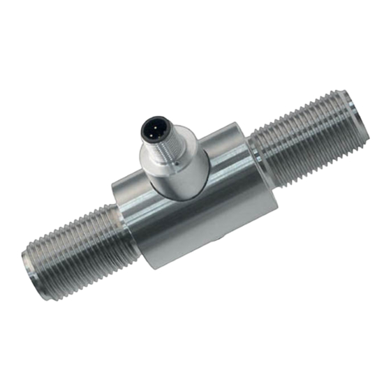
• Zug und/oder Druckkräfte werden bei der Baureihe F2301/F23C1/F23S1 über zwei axiale Gewindebolzen eingeleitet. • Die mitgelieferten Kontermuttern dürfen in keinem Fall am Verfor- mungskörper anliegen. • Zur Vermeidung von Störkräften empfiehlt tecsis die Verwendung von Gelenkköpfen (siehe Kap. 9). Abb. 4 Einbausituation eines Zug-/Druckkraftaufnehmers www.tecsis.de... -
Page 12: Elektrischer Anschluss
Um Einkopplungen von Störungen zu vermeiden beachten Sie bitte folgende Hinweise: • Verwenden Sie nur abgeschirmte, kapazitätsarme Messkabel (tecsis-Kabel, erfüllen diese Bedingungen). • Erden Sie das geschirmte Messkabel beidseitig. • Legen Sie die Messkabel nicht parallel zu Starkstrom- und Steuerleitungen. -
Page 13: Anschlussbelegung Analogausgang
OV/S- OV/S- 940E01 Standardversion 4…20 mA, 4…20 mA, 0…10 V, 2-Leiter 3-Leiter 3-Leiter Versorgung Versorgung 0V/UB- Signal Signal Gehäuse Gehäuse Gehäuse Schirm Kabelbelegung Kabelfarbe 2-Leiter 3-Leiter UB+/S+ 0V/S- 0V/S- Nur bei Verwendung der tecsis-Standardkabel, z. B. EZE53X011016 www.tecsis.de BD_BE_912 c... -
Page 14: Anschlussbelegung Version Atex/Iecex
Versorgung Versorgung 0V/UB- Signal Signal Gehäuse Schirm Kabelbelegung Kabelfarbe 2-Leiter UB+/S+ 0V/S- Nur bei Verwendung der tecsis-Standardkabel, z. B. EZE53X011016 Anschlussbelegung Version SIL-3 nach EN 62061:2005 4…20 mA, 4…20 mA, 0…10 V, 2-Leiter 3-Leiter 3-Leiter Versorgung Versorgung 0V/UB- Relais Relais... -
Page 15: Anschlussbelegung Analogausgang Redundant, Gegenläufig
Betriebsanleitung/Operating manual F2301/F23C1/F23S1 Anschlussbelegung Analogausgang redundant, gegenläufig 2-Stecker-Variante bspw. in Kombination mit ELMS1 Überlastsiche- rung (F23S1). Ausführung gem. Anforderung nach funktionaler Sicherheit gem. Maschinenrichtlinie 2006/42/EG. Rundsteckverbinder M12x1, 4-polig 4…20 mA/ 20…4 mA (redundant) Stecker 1 Stecker 2 Versorgung: UB+ Versorgung:... -
Page 16: Technische Daten
Betriebsanleitung/Operating manual F2301/F23C1/F23S1 Technische Daten Kurzzeichen Einheit Baureihe F2301 F23S1 Messbereich Nennkraft ab 1 Genauigkeit und Stabilität Relative Linearitätsabweichung ± 0,2 Relative Umkehrspanne < 0,1 Relatives Kriechen Temperatureinfluss auf das Nullsignal %/10 K Temperatureinfluss auf den Kennwert %/10 K Mechanische Kennwerte... - Page 17 Betriebsanleitung/Operating manual F2301/F23C1/F23S1 Kurzzeichen Einheit F23C1 Version F23C1 Version Baureihe ATEX/IECEx Ex ib SIL-3 nach EN 62061:2005 Messbereich Nennkraft ab 1 kN Genauigkeit und Stabilität Relative Linearitätsabweichung ± 0,2 Relative Umkehrspanne < 0,1 Relatives Kriechen Temperatureinfluss auf das Nullsignal %/10 K...
-
Page 18: Bemaßung
Betriebsanleitung/Operating manual F2301/F23C1/F23S1 Bemaßung Ausführung 1 - 30 kN ∅N- Nenn- Kugel Nenn- kraft (Nm) mess- 1,2,3 25,2 < 0,5 5 kN 25,2 < 0,5 10 kN 25,2 < 0,5 20 kN 25,2 M20x1,5 < 0,1 < 0,1 30 kN... - Page 19 Betriebsanleitung/Operating manual F2301/F23C1/F23S1 Ausführung ab 50 kN ∅C ∅N- Nenn- Kugel Nenn- kraft (Nm) mess- 50 kN M24x2 < 0,1 100 kN 19,5 M39x3 2500 < 0,1 Alle Angaben in mm www.tecsis.de BD_BE_912 c...
-
Page 20: Zubehör
Betriebsanleitung/Operating manual F2301/F23C1/F23S1 9 Zubehör Gelenkköpfe Nennkraft Mindest- einschraubtiefe 1, 2, 3, 5 kN 148±3 10 kN 155±3 20 kN 219±4 30 kN 226±4 50 kN 276±4 19,5 100 kN 405±7 Alle Angaben in mm Gelenkköpfe nach DIN ISO 12240-4, ∅D1= 12 bis 25 Massreihe K... - Page 21 Betriebsanleitung/Operating manual F2301/F23C1/F23S1 Kabel Kabeldose M12x1 Stecker l = 2m l = 5m l = 10m gerade EZE53X011010 EZE53X011012 EZE53X011010 4-polig mit Kabel gewinkelt EZE53X011011 EZE53X011013 EZE53X011010 gerade EZE53X011043 EZE53X011044 EZE53X011010 5-polig mit Kabel gewinkelt EZE53X011045 EZE53X011046 EZE53X011010 Andere Kabellängen und Kabelarten sind auf Anfrage erhältlich.
-
Page 22: Atex - Ausführung Ex Ib
Betriebsanleitung/Operating manual F2301/F23C1/F23S1 ATEX – Ausführung Ex ib 10.1 Information Diese Informationen ergänzen und ersetzen die Angaben aus der vorlie- genden Betriebsanleitung BD914_d. Sie gilt für ATEX - Geräte der Klas- sifizierung: EN 60079-0:2012/ EN 60079-11:2012 (Ex ib). II 2G Ex ib IIC T4 Gb -25°C <... -
Page 23: Störungsbeseitigung
Betriebsanleitung/Operating manual F2301/F23C1/F23S1 10.2 Störungsbeseitigung An Geräten, die in Verbindung mit explosionsgefährdeten Bereichen betrieben werden darf keine Veränderung vorgenommen werden. Re- paraturen am Gerät dürfen nur von speziell hierfür ausgebildetem und berechtigtem Fachpersonal ausgeführt werden. Defekte Geräte sind an den Hersteller zurückzusenden. -
Page 24: Konformitätserklärung
Betriebsanleitung/Operating manual F2301/F23C1/F23S1 Konformitätserklärung BD_BE_912 c www.tecsis.de... -
Page 25: Safety Note
The legal and safety regulations that apply to the respective application must also be observed during use (e.g. VDE 0100). This also applies to the use of accessories. Tecsis load cells are RoHS compliant acc. directive 2011/65 / EU article 2 para- graph (2) and paragraph (4) (d), (e) and (g). -
Page 26: General Dangers If The Safety Instructions Are Not Followed
F2301/F23C1/F23S1 General dangers if the safety instructions are not followed Load cells made by tecsis are manufactured in accordance with the lat- est state of technology and are safe during operation. However, the load cells can be the source of residual danger if they are used or operated improperly. -
Page 27: Operating Location Conditions
They are maintenance-free and can also be installed in locations that are difficult to access. The wide range of output signals allows tecsis load cells to be adapted to many difference usage conditions. As precision measuring devices, the load cells must be handled with care during transportation and assembly. -
Page 28: Design And Method Of Operation
Betriebsanleitung/Operating manual F2301/F23C1/F23S1 Design and method of operation Measuring element Innovative manufacturing methods using the DMS principle have recently been developed. Etched wire strain gauges are not used in this case. The entire Wheatstone bridge with the necessary equalization re- sistances and temperature compensation is realized using a thin-film method on a metallic, pot-shaped body. -
Page 29: Moisture And Corrosion Protection
Betriebsanleitung/Operating manual F2301/F23C1/F23S1 Moisture and corrosion protection Tropical climates and condensation are not a problem because the load cells comply with protection class IP 67 in accordance with EN 60529:1991+A1:2000 / IEC 529. The entire measuring spring is made from stainless steel. The amplifier casing with plug connection is made from aluminum. - Page 30 Betriebsanleitung/Operating manual F2301/F23C1/F23S1 Fig. 1 Name plate Standardversion - 1x connecting plug – output signal 4…20 mA Fig. 2 Name plate Atex version acc. EN 60079:0-2012: Ex ib acc. EN 60079-11:2012 - 1x connecting plug –output signal 4…20 mA Fig. 3 Name plate version SIL-3 acc. EN 62061:2005 - 1x connecting plug - output signal 4…20 mA...
-
Page 31: General Installation Guidelines
• The supplied lock nuts must not come into contact with the defor- mation body. • In order to avoid interfering force, tecsis recommends the use of ar- ticulated heads (see chapter 9). Fig. 4 Installation situation of a tension/compression load cell www.tecsis.de... -
Page 32: Electrical Connection
To avoid EMC problems, please note the following: • Always use shielded, low-capacity measuring cables (all tecsis cables meet these requirements). • The shielded measuring cable should be grounded on both sides. -
Page 33: Connection Assignment Analog Signal
4…20 mA, 0…10 V, 2-wire 3-wire 3-wire Power supply Power supply 0V/UB- Signal Signal Housing Housing Housing Shield Cable assignment cable colour 2-wire 3-wire UB+/S+ 0V/S- 0V/S- Only when using the tecsis standard cable, for example. EZE53X011016 www.tecsis.de BD_BE_912 c... -
Page 34: Connection Assignment Version Atex/Iecex
Signal Signal Housing Shield Cable assignment cable colour 2-wire UB+/S+ 0V/S- Only when using the tecsis standard cable, for example. EZE53X011016 Connection assignment version SIL-3 acc. EN 62061:2005 4…20 mA, 4…20 mA, 0…10 V, 2-wire 3-wire 3-wire Power supply Power supply... -
Page 35: Connection Assignment Analog Signal Redudant Opposing
Betriebsanleitung/Operating manual F2301/F23C1/F23S1 Connection assignment analog signal redundant opposing 2 round connectors option, for example, in combination with ELMS1 overload protection (F23S1). Version acc. the requirements for functional safety acc. Machinery Directive 2006/42/EG. Round connector M12x1, 4 pin 4…20 mA/ 20…4 mA (redundant) -
Page 36: Technical Data
Betriebsanleitung/Operating manual F2301/F23C1/F23S1 Technical data Symbol Unit Model series F2301 F23S1 Measurement range Rated force > 1 kN Accuracy and stability Relative linearity error ± 0.2 Relative reversibility error < 0.1 Relative creep Temperature effect on zero signal %/10 K... - Page 37 Betriebsanleitung/Operating manual F2301/F23C1/F23S1 Symbol Unit F23C1 Version F23C1 Version Model series ATEX/IECEx Ex ib SIL-3 nach EN 62061:2005 Measurement range Rated force > 1 kN Accuracy and stability Relative linearity error ± 0.2 Relative reversibility error < 0.1 Relative creep...
-
Page 38: Dimensions
Betriebsanleitung/Operating manual F2301/F23C1/F23S1 Dimensions Version 1 - 30 kN Counter nut MA see table ∅N- Nom. Bowl Nominal force (Nm) deflection 1,2,3,5 kN 25.2 < 0.5 10 kN 25.2 < 0.5 20 kN 25.2 M20x1.5 < 0.1 30 kN 27.5 27.5... - Page 39 Betriebsanleitung/Operating manual F2301/F23C1/F23S1 Version > 50 kN Counter nut MA see table ∅C ∅N- Nom. Bowl Nominal de- force (Nm) flection 50 kN M24x2 < 0.5 100 kN 19.5 M39x3 2500 < 0.5 All dimensions in mm www.tecsis.de BD_BE_912 c...
-
Page 40: Accessories
Betriebsanleitung/Operating manual F2301/F23C1/F23S1 Accessories Articulated heads Nom. T min. force srew in depth 1, 2,3,5 kN 148±3 10 kN 155±3 20 kN 219±4 30 kN 226±4 50 kN 276±4 19.5 100 kN 405±7 All dimensions in mm Swivel heads acc. DIN ISO 12240-4, ∅D1= 12 to 25 dimension column K... - Page 41 Betriebsanleitung/Operating manual F2301/F23C1/F23S1 Cables Cable socket, M12x1 l = 2m l = 5m l = 10m plug straight EZE53X011010 EZE53X011012 EZE53X011010 4-pin with cable angled EZE53X011011 EZE53X011013 EZE53X011010 straight EZE53X011043 EZE53X011044 EZE53X011010 5-pin with cable angled EZE53X011045 EZE53X011046 EZE53X011010 Other cable lengths and cable types are available on request.
-
Page 42: Atex Version Ex Ib
Betriebsanleitung/Operating manual F2301/F23C1/F23S1 Atex version Ex ib 10.1 Information This insert supplements and supersedes the information in the previous operating instructions BD914_d. It applies to explosion-proof equip- ment with following classification: 60079-0:2012/ EN 60079-11:2012 (Ex ib). II 2G Ex ib IIC T4 Gb -25°C <... -
Page 43: Fault Remedying
Betriebsanleitung/Operating manual F2301/F23C1/F23S1 10.2 Fault remedying Devices that are operated in potentially explosive areas must not be mod- ified. The devices may only be repaired by specially trained and author- ised experts. Defective devices should be returned to the manufacturer. -
Page 44: Declaration Of Conformity
Betriebsanleitung/Operating manual F2301/F23C1/F23S1 11 Declaration of Conformity BD_BE_912 c www.tecsis.de... - Page 45 Betriebsanleitung/Operating manual F2301/F23C1/F23S1 www.tecsis.de BD_BE_912 c...
- Page 46 Betriebsanleitung/Operating manual F2301/F23C1/F23S1 BD_BE_912 c www.tecsis.de...
- Page 48 GmbH Carl-Legien-Straße 40-44 63073 Offenbach am Main Germany Telefon: +49 69 5806-0 Fax: +49 69 5806-7788 E-Mail: info@tecsis.de Internet: www.tecsis.de...
Need help?
Do you have a question about the F2301 and is the answer not in the manual?
Questions and answers