
Summary of Contents for Tynetec Reach plus GSM
- Page 1 Reach Plus GSM At‐Home Alarm Unit Touch Personal Pendant USER & INSTALLATION GUIDE www.tynetec.co.uk ...
-
Page 2: Table Of Contents
SECTION 1 – USER INSTRUCTIONS Section Topic Page 1.1 Unpacking the Reach Plus GSM At‐Home Alarm 3 1.2 Important Information 3 1.3 The Touch Personal Pendant 4 1.4 Connecting the Reach Plus GSM At‐Home Alarm 5 1.5 Fitting the SIM Card 5 1.6 Switching the Reach Plus GSM At‐Home Alarm on 6 1.7 Fitting the GSM Base to the Reach Plus Unit 6 1.8 Signal Strength Test Mode 7 1.9 Switching the Reach Plus GSM At‐Home Alarm off 8 1.10 Making an Emergency Call 9 1.11 Accidental Calls 10 1.12 Answering an incoming Telephone Call 10 ... -
Page 3: Unpacking The Reach Plus Gsm At-Home Alarm
1.2 IMPORTANT INFORMATION If the user has electronic equipment it should be at least 2 metres away from the Reach Plus GSM unit. Failure to provide this separation may result in reduced range of personal pendants or other radio devices. When installing a Reach Plus GSM unit ensure all radio trigger devices including those that may have been previously installed e.g. smoke detectors, PIR's etc. are registered with the Reach Plus GSM unit. Once complete a test call should be raised from each trigger device to the Alarm Receiving Centre to ensure it is received and the trigger device is correctly identified. The Reach Plus GSM unit includes delicate electronics – to allow water to come into contact with it is dangerous and may cause damage. If the unit does get wet; un‐plug it from the mains supply and switch off immediately, then contact your Service Provider before attempting to re‐use it. You can dust the Reach Plus GSM or Touch Pendant with a soft cloth or soft brush. For particularly soiled units wipe clean with a damp cloth and a non‐abrasive cleaning product, polish with a dry duster. DO NOT use a wet cloth on the Reach Plus GSM unit. Avoid using harsh, abrasive or corrosive cleaning agents or detergents (e.g. scouring powders, bleaches, polishes, etc.) when cleaning the Reach Plus GSM or Touch Pendant. Both the Reach Plus GSM and Touch Pendant contain batteries and should therefore not be disposed of in domestic waste. Refer to Tynetec’s Telecare Battery Management information (Doc No. FM0630) for details on battery types, changing intervals and safe disposal. ‐ 3 ‐ ... -
Page 4: The Touch Personal Pendant
Making an Emergency Call… Simply press the Touch pendant button once. The button will FLASH RED (( )) for several seconds to confirm a call is being made. The Reach Plus GSM will announce “Pendant alarm – Please wait, dialling for assistance” The Touch pendant battery should last for about 3‐5 years depending on use. The battery condition is checked every day, if the voltage falls and stays below a preset level for 7 consecutive days a “low battery” call will automatically be sent to the Control Centre. Pendants must be returned to Tynetec for battery replacement. ‐ 4 ‐ ... -
Page 5: Connecting The Reach Plus Gsm At-Home Alarm
Reach Plus IMPORTANT GSM BASE AT‐HOME ALARM UNIT This aerial wire receives signals from radio devices and must not be cut‐down or coiled‐up Manufactured in the UK by tynetec REN 1.0 Receiver Frequency 169.48125MHz Complies with: ECC/DEC/(05)02 ETSI EN 300 220-2 Class 1 No user serviceable parts inside case. GSM DO NOT UNPLUG SWITCH OFF ANTENNA ... -
Page 6: Switching The Reach Plus Gsm At-Home Alarm On
1.6 SWITCHING THE REACH PLUS GSM AT‐HOME ALARM ON Connect the power lead to a mains socket and switch on; the front light will flash RED/AMBER/GREEN until the unit has attached to the Network… (( DO NOT UNPLUG SWITCH OFF ... -
Page 7: Signal Strength Test Mode
1.8 SIGNAL STRENGTH TEST MODE To check the Network signal strength follow the procedure below; 1. Press and HOLD the GREEN and YELLOW buttons TOGETHER… When the front light FLASHES FAST GREEN release the buttons and the unit will announce… “Radio Device Test” 2. Press the YELLOW button and the unit will announce… “Signal Strength” The front light will FLASH GREEN ... -
Page 8: Switching The Reach Plus Gsm At-Home Alarm Off
1.9 SWITCHING THE REACH PLUS GSM AT‐HOME ALARM OFF The Reach Plus GSM At‐Home Alarm uses very little power and should always be left switched ON. If it is necessary to switch the unit OFF follow the procedure below; 1. Turn the mains supply off and wait for the unit to announce… “Please check your mains supply” DO NOT UNPLUG SWITCH OFF 2. Press and HOLD the GREEN button until the unit “beeps” once… “Beep” 3. RELEASE the GREEN button and the unit will announce… “Powering down” ... -
Page 9: Making An Emergency Call
1.10 MAKING AN EMERGENCY CALL An emergency call can be made at any time of the day or night. 1. Press the RED (( )) button on the Reach Plus GSM unit or press the Touch pendant... The pendant button will OR FLASH RED (( )) for a ... -
Page 10: Accidental Calls
1.11 ACCIDENTAL CALLS If an emergency call is made by accident it can be cancelled by pressing the GREEN button once. The unit will announce “Alarm cancelled” and the front light will return to STEADY GREEN. “Alarm cancelled” Please note once the Reach Plus starts to dial the call cannot be cancelled. Advise the user not to worry if they don’t manage to cancel an accidental call – when the control centre answers they just need to say the call was made accidently. The staff will be pleased that they have talked and they will cancel the call in the normal way. 1.12 ANSWERING AN INCOMING TELEPHONE CALL The Reach Plus GSM can also be used to answer a normal incoming telephone call… ... -
Page 11: Using The Personal Recipient Mode
1.13 USING THE PERSONAL RECIPIENT MODE The Reach Plus GSM can be set to dial up to 4 different personal recipients (e.g. relatives or friends). The personal recipient telephone numbers (PR1‐PR4) must be programmed – see section 2.6.5 A personal recipient message must be recorded – see section 2.6.8 To answer a personal recipient call… When a mobile phone rings the display will Grandma RING Peterson normally show the name and number of the caller 019121447 (provided it is stored in the phonebook memory). 35 RING Pick‐up to answer in the normal way then… Press the star key once. ... -
Page 12: Using The Activity Monitoring Mode
1.14 USING THE ACTIVITY MONITORING MODE Optional PIR movement detectors can be installed in the home to monitor if the resident is “up and about” each day. If no movement is detected by the end of an activity monitoring period an inactivity alarm call will be sent to the control centre. If the resident is going away from home the Reach Plus GSM should be put into “Away Mode” to prevent inactivity calls being sent to the control centre. See section 1.19 for how to use the Away Mode. If no movement is detected the unit will announce… (( )) “Inactivity alarm” The GREEN button will FLASH GREEN and the message will repeat for 60 seconds. Press the FLASHING GREEN button once within 60 seconds… ... -
Page 13: Using The I'm Ok Mode
1.15 USING THE I’M OK MODE The Reach Plus GSM can be set to flash its GREEN button and sound a beep for a preset time period each day. If the resident is “up and about” and feeling “OK” they can press the GREEN button to stop the alert. If the GREEN button has not been pressed before the end of the I’m OK period an inactivity call will be sent to the control centre. If the resident is going away from home the Reach Plus GSM should be put into “Away Mode” to prevent inactivity calls being sent to the control centre. See section 1.19 for how to use the Away Mode. During the I’m OK period… The GREEN button will FLASH GREEN (( )) once per second. ... -
Page 14: Using The Activity Linked I'm Ok
1.16 USING THE ACTIVITY LINKED I’M OK Telecare sensors such as mains usage monitors, door contacts or PIR movement detectors can be used to monitor daily activity and automatically register the resident as being OK. For example; if a kettle fitted with a mains usage monitor is boiled during the I’m OK period this will stop the local alert and the resident will be registered as being “OK”. Activity linked I’m OK must be enabled during programming of the Reach Plus GSM – see section 2.6.6 for details. Care should be taken when using this option as the activation of any Telecare sensor during the I’m OK period will be recognised as activity and will therefore register the person as being OK. 1.17 USING THE I’M OK TIMEOUT ALERT The Reach Plus GSM can be set to play a user recorded speech message at the end of the I’m OK period if the green button has not been pressed (or if no activity has been detected). At the end of the I’m OK period… “Press the flashing green button now if you’re feeling (( )) OK today” ... -
Page 15: Using The Away Mode
1.19 USING THE AWAY MODE If activity monitoring or I’m OK mode is being used and the resident is going away from home they must select “Away Mode” to prevent in‐activity calls being sent to the control centre. Press the YELLOW button and the unit will announce… “Away” The front light will FLASH GREEN The unit is now in Away Mode – activity monitoring and I’m OK mode is turned off. When the resident returns home they must remember to turn activity monitoring and I’m OK back on... Press the YELLOW button and the unit will announce… “Home” The front light will go STEADY GREEN ... -
Page 16: Using The Intruder Mode
1.20 USING THE INTRUDER MODE If optional PIR movement detectors are fitted for activity monitoring the resident can use these devices as a basic intruder alarm when they go out. 1. Press the GREEN button and the unit will announce… “Intruder mode …Ready” 2. Press the TOUCH PENDANT within 20 seconds and the unit will announce… “Enabled” ‐ “Beep‐Beep” “Beep‐Beep”….. ... -
Page 17: Using The Reminder Mode
1.21 USING THE REMINDER MODE The Reach Plus GSM can be set to play a reminder message at the same time every day, once a week or once a month. Up to 8 different messages, maximum 8 seconds duration each, can be recorded by a Carer or relative using the microphone in the unit. The reminder message will repeat for 30 seconds or it can be silenced by pressing the GREEN button. When it’s time a reminder message will play… “Don’t forget to take your pills this morning” (( )) The GREEN button will FLASH GREEN and the reminder will repeat for 30 seconds. Press the FLASHING GREEN button once… ... -
Page 18: Using The Low Temperature Alert Mode
1.22 USING THE LOW TEMPERATURE ALERT MODE If an optional Ambient Temperature Sensor is fitted the Reach Plus GSM can be set to play a user recorded message if the room temperature falls below the upper set point. If the room temperature continues to fall below the lower set point an SMS text message will be sent to a Responder. The Reach Plus GSM can be set to monitor the room temperature during 3 pre‐set time periods each day. If the room temperature falls below the upper set point a message will play … “Turn the heating on now, your house is getting cold” Press the GREEN button once to silence the message… ... -
Page 19: Using The Door Monitoring Mode
1.23 USING THE DOOR MONITORING MODE If optional door contacts are fitted the Reach Plus GSM can be set to play a message and/or raise an alarm when an entrance door is opened. Up to 16 different messages, maximum 8 seconds duration each, can be recorded by a Carer or relative using the microphone in the unit. The Reach Plus GSM can be set to monitor the door permanently or during 3 preset time periods each day. If the entrance door is opened during a monitored period… “The front door is open” Press the GREEN button once to silence the message… ... -
Page 20: Using The Lone Worker Mode
1.24 USING THE LONE WORKER MODE The Reach Plus GSM can be set to sound an alert after a preset time interval has elapsed. The user has 60 seconds to press the GREEN button to stop the alert and re‐start the time interval again. If the GREEN button is not pressed after 60 seconds an inactivity call will be sent to the control centre. At the end of the Lone Worker interval… “Beep‐Beep‐Beep..” (( )) The GREEN button will FLASH GREEN and the unit will “Beep” for 60 seconds. Press the FLASHING GREEN button once… ... -
Page 21: Using The Carer Response Mode
1.25 USING THE CARER RESPONSE MODE The Reach Plus GSM can be used in a local care environment to monitor multiple residents with multiple Telecare sensors. The total number of sensors per Reach Plus GSM is 32. The Carer Response mode can be set to operate in one of two ways; 1: When a Telecare sensor is activated send an SMS text to a Responder followed by an alarm call to a Control Centre or Personal Recipient, or... 2: When a Telecare sensor is activated send an SMS text to a Responder, if the call is acknowledged within a pre‐set time (0‐9999 seconds) the alarm will be cancelled. If the text is not acknowledged the alarm will then report to a Control Centre or Personal Recipient. The SMS text message will identify the Reach Plus unit ID, the alarm type, the residence number, the location of the sensor and the time & date of the call. If option 2 is selected the call can be cancelled by replying OK within the preset time. When a sensor is activated a text message will be sent with the details below… Reach Plus unit ID (12 digits) Alarm type (i.e. type of sensor activated) Reach 000000139522 Pullcord Alarm Residents room/flat number Residence 14 Bathroom Location of sensor (from BS8521 options 00‐99) ... -
Page 22: Mains Power Failure Alert
1.26 MAINS POWER FAILURE ALERT The Reach Plus GSM will make the resident aware if their mains electricity is off or if the power lead has been accidently unplugged... The front light will FLASH AMBER and the unit will announce… “Please check your mains supply” This message will repeat 3 times every 4 hours until the mains power is restored. To silence the message and prevent it repeating again, press the GREEN button. ... -
Page 23: Battery Failure Alert
Press the GREEN button to SILENCE the message The low battery condition is automatically reported to the control centre and they will arrange to visit and replace the battery. In normal use the battery should not need replacing for between 3 to 5 years. The replacement battery must be identical to that originally fitted and should only be changed by a competent person. Replacement battery: Tynetec Part No. F00141 1.29 ON/OFF SWITCH The Reach Plus can be switched off if it is not going to be used for a prolonged period. Remove the GSM stand to access the battery cover on the rear of the Reach Plus unit. Undo the screw, remove the cover and carefully lift the battery out of its compartment. ... -
Page 24: Gsm Configuration Options
3. Program the Control Centre (or Personal Recipient) telephone number(s) 4. Set the Control Centre protocol type 5. Set the time & date Voice and SMS Text… This allows voice communications with a traditional Control Centre or Personal Recipient via the mobile network and also includes the ability to send and receive text messages from Carers or Responders. 1. Insert a voice & SMS enabled SIM card 2. Program a unit ID 3. Program the Control Centre (or Personal Recipient) telephone number(s) 4. Set the Control Centre protocol type 5. Program the mobile telephone number(s) for SMS text alerts 6. Set the time & date Voice, SMS Text and iCare… This allows voice communications with a traditional Control Centre or Personal Recipient via the mobile network, the ability to send and receive text messages from Carers or Responders and lifestyle monitoring via Tynetec’s iCare Server. 1. Insert a voice, SMS and iCare enabled SIM card 2. iCare Account set‐up with Tynetec 3. Program a unit ID 4. Program an iCare ID 5. Program the Control Centre (or Personal Recipient) telephone number(s) 6. Set the Control Centre protocol type 7. Program the mobile telephone number(s) for SMS text alerts 8. Program the IP Address and Port Number for iCare (default Tynetec Server) 9. Set the time & date Note: the iCare enabled SIM must be provided by Tynetec as it uses a secure private network to carry the data. 2.2 PROGRAMMING MODE OPTIONS ... -
Page 25: Keypad Programming Mode
2.3 KEYPAD PROGRAMMING MODE The keypad on the rear of the Reach Plus GSM can be used to program the majority of features, there are some that can only be programmed via SMS text. Enter 1 6 7 0 using the keypad on the rear… The front light will FLASH FAST GREEN and the unit will announce… ... -
Page 26: Setting The Telephone Number
2.3.2 SETTING THE TELEPHONE NUMBER The telephone number will be issued by the control centre (max 12 digits). Press # 0 2 6 and the unit will announce... “Telephone number 1” Enter the telephone number then press # If the number was entered correctly you will hear the “Ready” prompt. ... -
Page 27: Setting The Time & Date
2.3.4 SETTING THE TIME & DATE The time & date must be set so all events are logged with the correct time and all timed functions operate correctly. Press # 0 4 4 and the unit will announce... “Set Time” Enter the time as 4 digits using the 24 hour clock format (e.g. 1:30PM is 1330) followed by #. If the time was entered correctly you will hear ... -
Page 28: Sms Text Programming
2.4 SMS TEXT PROGRAMMING Many of the Reach Plus GSM features that are programmed via the keypad can also be setup using SMS text from a mobile phone. Note; there are some parameters that can ONLY be programmed via SMS text, see the Parameter List in section 2.6 and check the parameter required has an “S” (for SMS Text) in the Program Method column. Texts must start with TYNETEC (in CAPS) followed by a space, then the 4 digit security code (default 7777) followed by a space, then the parameter number which always begins with a # (e.g. #026), followed by the new data followed by #, then send. Multiple parameters can be programmed in a single text provided the 160 character SMS text limit is not exceeded. For example; to program ARC telephone number 1 (parameter #026) to 01670352371 via text; T Y N E T E C 0 7 7 7 7 # 0 2 6 0 1 6 7 0 3 5 2 3 7 1 # ... -
Page 29: Programming Parameters List
2.6 PROGRAMMING PARAMETERS LIST Parameter Program Default See Menu Group Parameter Enter the following data… Number Method Setting Section Load Defaults #000 Load System Defaults #001 Load Enter the required default parameter Load Radio Defaults #002 2.6.1 followed by # Defaults Load Log Defaults #018 Load Message Defaults #019 Siren Volume #005 K+S+C Level 3 Enter 0 to 5 followed by # Audio Volume #006 K+S+C Level 3 0# = off, 5# = max volume ... - Page 30 2.6 PROGRAMMING PARAMETERS LIST – CONTINUED Parameter Program Default See Menu Group Parameter Enter the following data… Number Method Setting Section Safe Call Setup #039 0# = Disable or 1# = Enable Disabled 0 = Disable or 1 = Enable Disabled Optional Intruder Mode Setup #063 K Entry time 000 to 999 Secs 30 Sec Entry 2.6.9 Exit time 000 to 999 Secs then # 30 Sec Exit Settings Tx Event to Data Collector #043 0# = Disable or 1# = Enable Disabled Change Security Code #125 Enter new 4 digit code followed by # 1670 ...
- Page 31 Voice GSM Mode #152 K+S 2# = Voice+iCare, 3# = iCare Only Only GSM Security Code #160 4 Digit Code for SMS Programming 7777 2.6.14 Wirelesslogic‐ APN (Access Point Name) #172 S Network Provider Name hsdpa.co.uk APN User ID #173 Network Provider ID tynetec APN Password #174 Network Provider Password tynetec Mobile Tel No.1 (Responder) #161 None Mobile Tel No.2 (Responder) #162 None Mobile Tel No.3 (Responder) #163 None GSM Setup Mobile Tel No.4 (Responder) #164 None Enter Mobile Tel No’s for SMS Text (max 16 Mobile Tel No.5 (Carer) #165 digits) followed by # ...
-
Page 32: Load Defaults
2.6.1 LOAD DEFAULTS Load Defaults – clears all parameter settings, radio devices, Telecare data and recorded messages from the Reach Plus GSM memory. Enter #000, the unit will announce “Load Defaults” then press #. Load System Defaults – clears all parameter settings from the Reach Plus GSM memory. Enter #001, the unit will announce “Load System Defaults” then press #. Load Radio Defaults – clears all radio devices from the Reach Plus GSM memory. Enter #002, the unit will announce “Load Radio Defaults” then press #. Load Log Defaults – clears all stored Telecare data from the Reach Plus GSM memory. Enter #018, the unit will announce “Load Log Defaults” then press #. Load Message Defaults – clears all recorded messages from the Reach Plus GSM memory. Enter #019, the unit will announce “Load Message Defaults” then press #. 2.6.2 AUDIO SETTINGS Siren Volume – the volume of all alarm messages and dial‐out tones can be set between 0 (off) and 5 (highest). Enter #005, the unit will announce “Siren Volume”, press 0 to 5 followed by #. Audio Volume – the speech volume to/from the control centre can be set between 0 (off) and 5 (highest). Enter #006, the unit will announce “Audio Volume”, press 0 to 5 followed by #. Ring Volume – the volume of the internally generated ring tone (this is only used if there is no telephone connected to the TEL socket) can be set between 0 (off) and 5 (highest). Enter #007, the unit will announce “Ring Volume”, press 0 to 5 followed by #. Audio Mode – allows the control centres method of switching the speech to be set. Simplex means the speech direction is manually switched whereas Half Duplex is voice switched. Note; always check with the control centre which method they prefer to use. Enter #008, the unit will announce “Audio Mode”, press 0# for Simplex or 1# for Half Duplex. Mains Fail Alert – allows the audible “Please Check Your Mains Supply” message to be turned on/off. A mains failure is reported to the control centre after a random delay between 1 and 4 hours. Enter #009, the unit will announce “Mains Disconnection Alert”, press 0# to Disable or 1# to Enable. Assurance Tone – allows the audible “Please Wait – Dialling for Assistance” message and dial‐out tones to be turned on/off. Enter #010, the unit will announce “Assurance Tone”, press 0# to Disable or 1# to Enable. ... -
Page 33: Hardwired Inputs & Output
2.6.3 HARDWIRED INPUTS & OUTPUT Up to two hardwired inputs and one relay output can be connected to the Reach Plus GSM using a special hardwired I/O unit – Tynetec Part No. ZSA557. The change‐over clean contact relay output can be activated from the control centre during a call. The DTMF tone used to activate the relay and the duration it remains latched is programmable. All input devices must have normally open clean contacts which close on alarm except PIR’s which must have normally closed clean contacts which open on alarm. Hardwired Input 1 – enter #101, the unit will announce “Hardwired Input 1 – Trigger Type” Enter the device type (0 to 9) from the list below; 0 Not Assigned 1 Pullcord Smoke Detector PIR Detector 4 Door Contact 5 High Temp 6 Low Temp Gas Detector Heat Detector 9 CO Detector The unit will announce “Location Code” For units set on BS8521 protocol enter the 2 digit location code from the table below; For units set on TT or BS7369 protocol press #. 00 Not Assigned 13 Living Area ... -
Page 34: Identity Settings
2.6.4 IDENTITY SETTINGS Protocol Type – check with the control centre which protocol type they use. Enter #022, the unit will announce “Protocol Type” press 0# for TT or 1# for BS8521 or 2# for BS7369. BS7369 Interval – if BS7369 protocol is selected you can change the data interval for use on different Mobile networks. Enter #023, the unit will announce “BS7369 Interval Time”, enter the time required in mS as a 4 digit number (0001 to 9999) followed by #. Unit Identity – the unique ID number issued by the control centre to identify the users name, address and personal details. Enter #024, the unit will announce “Unit ID”, enter the ID number (maximum 12 digits) followed by #. Pre‐Alarm Delay – the time allowed for an emergency call to be cancelled (by the GREEN button) before the Reach Plus starts to dial the control centre. Enter #025, the unit will announce “Pre‐Alarm Delay”, enter the delay in seconds 00 (no delay), 04, 08, etc. to 60 in 4 second intervals followed by #. 2.6.5 TELEPHONE NUMBERS ARC1 to ARC4 – these are the Alarm Receiving Centre (control centre) telephone numbers. Enter #026, the unit will announce “Telephone Number 1”, enter the telephone number (max 16 digits) followed by #. Repeat for ARC telephone numbers 2, 3 & 4. Enter a between digits to incur a pause in dialling. To delete a telephone number; enter the Parameter Number followed by #. For example to delete ARC3 enter #028#. PR1 to PR4 – these are the Personal Recipient (relative/friend) telephone numbers. Enter #030, the unit will announce “Telephone Number 5”, enter the telephone number (max 16 digits) followed by #. Repeat for PR telephone numbers 6, 7 & 8. If PR telephone numbers are used a “unit identity message” should be recorded – see section 2.3.8. ARC1 to ARC4 Dial Attempts – the number of times each ARC telephone number will be dialled if it gets an engaged tone on the first attempt. Enter #03826, the unit will announce “Telephone Number 1 Dial Attempts”, press 1 to 9 followed by #. Repeat for ARC telephone numbers 2, 3 & 4. PR1 to PR4 Dial Attempts – the number of times each PR telephone number will be dialled if it gets an engaged tone on the first attempt. Enter #03830, the unit will announce “Telephone Number 5 Dial Attempts”, press 1 to 9 followed by #. Repeat for PR telephone numbers 6, 7 & 8. Dial Sequence – the order in which the 8 telephone numbers (4 ARC and 4 PR) are dialled. 1‐4 represent the ARC numbers and 5‐8 represent the PR Numbers. Enter #037, the unit will announce ... -
Page 35: Activity Monitoring
2.6.6 ACTIVITY MONITORING The activity monitoring mode allows the Reach Plus GSM to monitor residents movement over 3 preset periods per day and automatically report an alarm at the end of each period if there has been no activity (or less activity than the preset minimum threshold). The activity threshold can range from 00 to 99 – this is the minimum number of PIR activations you would expect to see during the activity monitoring period. Enable/Disable – a PIR detector (hardwired or radio) must be fitted if activity monitoring is being enabled. Enter #034, the unit will announce “Activity Monitoring”, press 0# to Disable or 1# to Enable. Activity Period 1 Setup – set activity monitoring period 1 start time, threshold and stop time. Enter #0351, the unit will announce “Activity Monitoring Setup 1 – Start Time” Enter the start time as 4 digits using the 24 hour clock format (e.g. 7AM is 0700) The unit will announce “Threshold” Enter the threshold as a 2 digit number (00 to 99) The unit will announce “Stop Time”. Enter the stop time as 4 digits using the 24 hour clock format (e.g. 10AM is 1000) followed by #. Activity Period 2/3 Setup – enter #0352/#0353 to set activity monitoring periods 2/3 and follow the same procedure as above. Inactivity Reminder – if the inactivity reminder is enabled an “inactivity alarm” message will play at the end of the monitored period if no activity (or less than the preset threshold) has occurred. The user has 60 seconds to confirm activity by pressing the GREEN button once, if the button is not pressed an inactivity alarm will be reported. Enter #071, the unit will announce “Inactivity Reminder”, press 0# to Disable or 1# to Enable. Lone Worker Interval – if the lone worker interval is set the unit will start to beep after the preset time interval has elapsed. The user has 60 seconds to confirm they are OK by pressing the GREEN button once, if the button is not pressed an inactivity alarm will be reported. Enter #072, the unit will announce “Lone Worker”, enter the interval as a single digit in hours (1 to 9) followed by # or enter 0# to disable the feature. I’m OK Setup – if the I’m OK feature is set the unit will flash its GREEN button and sound a beep during a preset time period each day. During this period the user can press the GREEN button once to declare themselves “OK”. If the button is not pressed an inactivity alarm will be reported after a random delay up to 1 hour after the end of the I’m OK period. Note: the GREEN button will flash for the entire I’m OK period whereas the beep will only sound once every 5 minutes for the last 30 minutes then once a minute for the last 5 minutes of the period. Alternatively the GREEN button flash and/or audible beep can be turned off. ... -
Page 36: Periodic Test
2.6.7 PERIODIC TEST The Reach Plus GSM has the option to perform an automatic test call on a preset interval between 1 and 99 days. The time the test call is made is also programmable. Note: the user will not know when a test call is being performed, the dial‐out is silent and no speech is heard. Periodic Test – set the interval between test calls and the time of day you want the call to be made. Enter #036, the unit will announce “Periodic Test – Interval” Enter 2 digits (01 to 99) for the interval between test calls in days The unit will announce “Time” Enter the test call time as 4 digits using the 24 hour clock format (e.g. 8PM is 2000) followed by #. Note: do not set multiple Reach Plus GSM units with a periodic test call to the same control centre with the same interval and time. Try and choose a “quiet” time of the day to send the test call. To disable a periodic test set the interval as 00. 2.6.8 MESSAGES SET‐UP The internal microphone on the Reach Plus unit can be used to record a personal recipient message and up to 16 other general messages. Each message is limited to a maximum of 8 seconds duration. It is important that a clear, preferably high pitched, voice is used at normal conversation level – do not shout. The message should be spoken clearly and deliberately so that it will be easily understood by the alarm recipient. Record ID Message – allows a personal recipient message to be recorded. This message will be heard over the phone by the person that answers the emergency call. Enter #060, the unit will announce “Record ID Message” After the countdown of 3 beeps speak your message (max 8 secs) Press # to end recording or the unit will announce “Ready” when the record time has expired. Play ID Message – the personal recipient message will be played‐back. Enter #061, the unit will announce “Play ID Message”, after the single beep your message will be heard. Delete ID Message – the personal recipient message will be deleted. Enter #062, the unit will announce “Delete ID Message”, after the single beep press #. ... -
Page 37: Options Setup
If you enter 1 or 2 the unit will announce “Day” Enter the day you want the reminder to play each week or month as a single digit (1 = Mon to 7 = Sun) The unit will announce “Acknowledge” Enter 1 for Yes or 0 for No; if set as 1 (Yes) the GREEN button can be pressed to silence the reminder message, if set as 0 (No) the reminder will repeat for 30 seconds then stop. The unit will announce “Alarm” Enter 1# for Yes or 0# for No; if set as 1# (Yes) then an inactivity alarm will be reported after 60 seconds if the reminder is not acknowledged by pressing the GREEN button. If set as 0# (No) then the reminder message will repeat for 30 seconds only. Enter #092 to #098 to setup reminders 2 to 8. For example: to set a reminder every Tuesday for lunch club at 11:45AM, acknowledgement is required with an alarm call to the control centre if it is not acknowledged… The message has been recorded by a family member in message number 2 slot Enter #091 02 (message slot 2) and the unit announces “Time” Enter 1145 (11:45AM in the 24 hour format) and the unit announces “Interval” Enter 1 (for weekly interval) and the unit announces “Day” Enter 2 (for Tuesday) the unit announces “Acknowledge” Enter 1 (for yes to require acknowledgement) and the unit announces “Alarm” Enter 1 (for yes to alarm) then press # and the unit announces “Ready” The reminder settings have been saved. 2.6.9 OPTIONS SET‐UP Safe Call Setup – Safe Call devices (Tynetec Part No. ZSA260) must be plugged in‐line with all telephones within the home if this option is enabled. These devices ensure the Reach Plus always takes control of the telephone line in an emergency situation. Enter #039, the unit will announce “Safe Call Setup”, press 0# to Disable or 1# to Enable. Intruder Mode Setup – a PIR movement detector must be installed if intruder mode is being enabled. Enter #063, the unit will announce “Intruder Mode” Enter 0# to disable or 1 to enable; if you press 1 to enable the unit will announce “Entry Time” Enter the entry time in seconds as 3 digits (000 to 999) The unit will announce “Exit Time” Enter the exit time in seconds as 3 digits (000 to 999) followed by #. ‐ 37 ‐ ... -
Page 38: Radio Device Setup
2.6.9 OPTIONS SET‐UP ‐ CONTINUED Change Security Code – the 4 digit security code required to enter programming mode via the keypad on the rear of the Reach Plus can be changed. Enter #125 and the unit will beep once, enter a new 4 digit code followed by #. Transmit Event to Data Collector – if enabled all events are transmitted on the Reach Plus data port for collection and analysis. Enter #043, the unit will announce “Transmit Event to Data Collector”, press 0# to Disable or 1# to Enable. 2.6.10 RADIO DEVICE SET‐UP For Reach Plus GSM units set on BS8521 protocol each radio device can be assigned a “Location Code” to allow the control centre operator to identify the exact location of the device in alarm. 00 Not Assigned 13 Living Area Utility Room 2 Games Room 52 Garden Other 01 Local Unit 14 Dining Room 1 Entrance/Lobby Common Room 1 53 Basement/Cellar 02 Hallway Down 15 Dining Room 2 Front Door 1 Common Room 2 54 Ground Floor 03 ... - Page 39 Enter 1 for Yes or 0 for No; if set as 1 (Yes) then an emergency call will be initiated when the input is activated, if set as 0 (No) then the alarm message will repeat for 30 seconds only The unit will beep, activate another radio device to be learned or press # to end. Radio devices can be set to only activate alarm calls during preset times (activity windows) each day. If they are activated outside these time periods the event is logged in the Reach Plus memory. Up to 3 activity windows can be set per device, they repeat every day and they can be set through midnight. Trigger Activity Window – allows a radio device to be learned automatically, have its location code, acknowledge & alarm parameters and activity windows assigned. Enter #051, the unit will announce “Learn Radio Device and Enter Location Code” Activate the radio device – the unit will announce “Device Type – Enter Location Code” Enter a 2 digit location code from the table above The unit will announce “Message Number” Enter a recorded message number (01 to 16) or enter 00 if no message is required The unit will announce “Acknowledge” Enter 1 for Yes or 0 for No; if set as 1 (Yes) the GREEN button can be pressed to silence the alarm message, if set as 0 (No) the message will repeat for 30 seconds The unit will announce “Alarm” Enter 1 for Yes or 0 for No; if set as 1 (Yes) then an emergency call will be initiated when the input is activated, if set as 0 (No) then the alarm message will repeat for 30 seconds only The unit will announce “Start Time 1” Enter start time 1 as 4 digits using the 24 hour clock format (e.g. 7AM is 0700) The unit will announce “Stop Time 1” Enter stop time 1 as 4 digits using the 24 hour clock format (e.g. 10AM is 1000) The unit will announce “Start Time 2”, enter start time 2 or if not required press # to exit. Trigger Action – only relevant to Carer pendants (Tynetec Part No. ZXT607), this allows attendance times to be logged in local memory with an alarm call to the control centre or to be logged in local memory only. If a Carer pendant is learned via the GREEN button you will get log only setup. Enter #050, the unit will announce “Learn Radio Device and Enter Location Code” Activate the Carer pendant and the unit will announce “Trigger Action” Enter 0# for log only or 1# for dial and log. ‐ 39 ‐ ...
-
Page 40: Buttons And Led Setup
2.6.10 RADIO DEVICE SET‐UP ‐ CONTINUED Auto‐Learn Second Pendant – for a second resident pendant, Enter #052 and follow the same procedure as #050 above. Note: you can only have one second resident pendant, if another is learned the first will revert to a standard pendant. Second Pendants are only recognised by Control Centres using TT or BS8521 protocol. Auto‐Learn Carer Response Radio Devices – if the Reach Plus GSM is being used in Carer Response mode then all radio devices must be assigned a residence number. Enter #053 and follow the same procedure as #050 above, an additional option is added at the end… After the “Alarm” is set the unit will announce “Residence Number” Enter a 2 digit residence number 00‐99 followed by #. The unit will beep, activate another radio device to be learned or press # to end. 2.6.11 BUTTONS AND LED SET‐UP The 3 push buttons, their illuminated halos and the tricolour status indicator light on the front of the Reach Plus unit can be individually enabled or disabled. Enter #064, the unit will announce “Program Red Button”, enter 0# to Disable or 1# to Enable. Enter #065, the unit will announce “Program Yellow Button”, enter 0# to Disable or 1# to Enable. Enter #066, the unit will announce “Program Green Button”, enter 0# to Disable or 1# to Enable. Enter #067, the unit will announce “Program Red LED”, enter 0# to Disable or 1# to Enable. Enter #068, the unit will announce “Program Tricolour LED”, enter 0# to Disable or 1# to Enable. Enter #069, the unit will announce “Program Yellow LED”, enter 0# to Disable or 1# to Enable. Enter #070, the unit will announce “Program Green LED”, enter 0# to Disable or 1# to Enable. 2.6.12 TIME & DATE SET‐UP The Reach Plus has a real time clock which must be set for all timed functions to operate correctly. Set Time – allows the time to be set. Enter #044, the unit will announce “Set Time” Enter the time as 4 digits using the 24 hour clock format (e.g. 1:30PM is 1330) followed by #. ... -
Page 41: Check Parameters
2.6.13 CHECK PARAMETERS The Reach Plus GSM programming can be checked by entering parameter check codes, all settings for each parameter group will be announced. Check Parameters – enter #003, the unit will announce “Check Parameters” followed by the unit ID, telephone numbers, protocol type, pendant ID (plus any other radio devices learned into the unit) and the software revision. Check Audio Settings – enter #080, the unit will announce “Check Audio Settings” followed by all settings listed in section 2.6.2. Check I/O Devices – enter #081, the unit will announce “Check Hardwired Input & Output” followed by all settings listed in section 2.6.3. Check Activity Monitoring – enter #082, the unit will announce “Check Activity Monitoring” followed by all settings listed in section 2.6.6. Check Periodic Test Call – enter #083, the unit will announce “Check Periodic Test Call” followed by all settings listed in section 2.6.7. Check Reminders – enter #084, the unit will announce “Check Reminders” followed by all settings listed in section 2.6.8. Check Optional Settings – enter #085, the unit will announce “Check Optional Settings” followed by all settings listed in section 2.6.9. Check Time & Date – enter #086, the unit will announce “Check Time & Date” followed by all settings listed in section 2.6.12. Check Trigger Window – enter #087, the unit will announce “Check Trigger Window” followed by all settings listed in section 2.6.10 (page 39). Check GSM Settings – enter #088, the unit will announce “GSM Setup” followed by all settings listed in section 2.6.14 to 2.6.17. 2.6.14 GSM SETUP ... -
Page 42: Mobile Telephone Numbers
Programmable ‐ sent after I’m ok window expires & no activity recorded House is at Low Temp Programmable ‐ sent if temperature at house is detected below 10 degrees Responder Alarm to Report Programmable ‐ Carer Response mode Person is Active Programmable ‐ sent after I’m ok window expires & activity is recorded Responder Person is Away Programmable ‐ sent if person puts unit into away mode and Carer Person is Home Programmable ‐ sent if person puts unit into home mode 2.6.16 I‐CARE SETUP If the Reach Plus GSM is being used with Tynetec’s iCare lifestyle monitoring software then an iCare Account ID along with the IP Address and Port Number of the Tynetec Server must be set. iCare ID – iCare account number issued by Tynetec. Enter #140, the unit will announce “GSM Data ID”, enter the 12 digit ID number followed by #. iCare IP Address – IP Address of the Tynetec Server. Enter #150, the unit will announce “IP Address”, enter the full 12 digit number (padded with zero’s) followed by #. For example; IP Address 82.69.230.11 would be entered as 082069230011. iCare Port Number – Port Number of the Tynetec Server. Enter #151, the unit will announce “Port Number”, enter the port number (max 6 digits) followed by #. ‐ 42 ‐ ... -
Page 43: Gsm Enhanced I'm Ok Setup
2.6.17 GSM ENHANCED I’M OK SETUP If Activity Linked I’m OK is being used the option of sending SMS text messages for home/away mode, low temperature and activity/no activity can be set. The option of reporting inactivity to the Control Centre or Personal Recipient is also set here. These options can only be enabled/disabled via SMS text. Enhanced I’m OK ‐ text #170 followed by a 4 digit code made up of 1’s and 0’s (where 1 = enabled and 0 = disabled) followed by #. Default is all enabled (1111). T Y N E T E C 0 7 7 7 7 # 1 7 0 1 0 1 0 # Home/Away Mode SMS: 1 = Yes 0 = No Low Temperature SMS: 1 = Yes 0 = No Activity/No Activity SMS: 1 = Yes 0 = No ... -
Page 44: Radio Device Learn Mode
2.7 RADIO DEVICE LEARN MODE The Touch pendant is pre‐learned in the factory, any additional pendants or other Telecare radio devices must be learned into the Reach Plus GSM before they can be used. If the Control Centre requests that the Telecare devices have “Location Codes” or if you want to assign devices to trigger reminder messages instead of alarms etc. then they must be learned via the Keypad Programming Mode ‐ see section 2.6.10. If you DO NOT require location codes or other special functions then follow the instructions below; 1. Press and HOLD the GREEN button… When the front light FLASHES FAST GREEN release the button and the unit will announce… “Trigger radio device” ... -
Page 45: Radio Device Test Mode
2.8 RADIO DEVICE TEST MODE The radio device test mode can be used to check the radio coverage of the Touch pendant and any other Telecare radio devices from all extremes of the dwelling. 1. Press and HOLD the GREEN and YELLOW buttons TOGETHER… When the front light FLASHES FAST GREEN release the button and the unit will announce… “Radio device test” 2. Go to all extremes of the dwelling and activate the pendant, the Reach Plus GSM will beep each time a radio signal is received OK. Repeat the test for all radio devices. 3. Press the GREEN button to exit radio device test mode… The front light will go STEADY GREEN ... - Page 46 NOTES ...
-
Page 47: Specification
2.9 SPECIFICATION Power Supply 220‐240V AC 50Hz <5 Watts Power Lead 12V 1.25A UK in‐line SMPSU (3.4 metre lead) GSM Base Quad‐Band 2G wireless module SIM Card 2G Mini‐SIM for attachment to the GSM network GSM Antenna 230mm high with magnetic base, 3 metre cable & SMA plug Battery Standby Daily self‐test, min 24 hours normal operation, 3‐5 year life (typical) Battery Type 6V 1800mAh NiMH Pendant Battery 3‐5 year life (typical) Pendant Frequency 169.48125 MHz (ETSI EN 300 220‐2) Class 1 (ECC/DEC/(05)02) Speech Control ... -
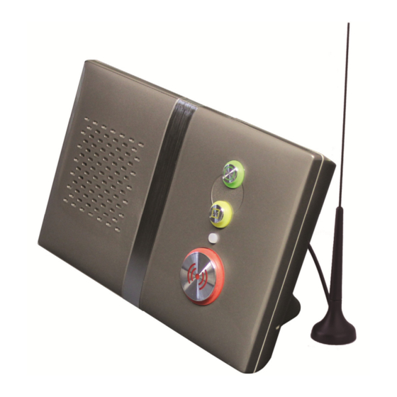
Page 48: Pushbutton And Status Light Quick Guide
Flashing Fast Green = Program Mode Steady Red = Emergency Call Flashing Red = Telephone Call Steady Amber = Intruder Mode Flashing Amber = Fault RED (()) EMERGENCY BUTTON Flashing Red Green = Data Download Used to make an EMERGENCY alarm call NEED MORE HELP OR ADVICE ? Please contact Tynetec’s Telecare Helpline on 01670 369934 Lines open Monday to Friday from 9AM to 5PM (excluding Bank Holidays) Cowley Road, Blyth Riverside Business Park, Blyth, Northumberland, NE24 5TF Email: sales@tynetec.co.uk Website: www.tynetec.co.uk ...
Need help?
Do you have a question about the Reach plus GSM and is the answer not in the manual?
Questions and answers