Table of Contents
Advertisement
Quick Links
GETTING STARTED GUIDE
PXI/PCI-5152
2 GS/s Oscilloscope
Note
Before you begin, install and configure your chassis and controller.
This document explains how to install, configure, and test the PXI/PCI-5152. The
PXI/PCI-5152 high-speed oscilloscope features 300 MHz analog bandwidth and up to 2 GS/s
real-time sample rate (20 GS/s equivalent-time sample rate for repetitive signals).
To access PXI/PCI-5152 documentation, navigate to Start»All Programs»National
Instruments»NI-SCOPE»NI-Scope Documentation.
Caution
in a manner not described in this document.
Contents
Electromagnetic Compatibility Guidelines............................................................................... 2
Verifying the System Requirements..........................................................................................2
Unpacking the Kit..................................................................................................................... 2
Kit Contents...................................................................................................................... 3
Other Equipment....................................................................................................................... 3
Preparing the Environment....................................................................................................... 4
PXI Modules..................................................................................................................... 4
PCI Modules..................................................................................................................... 4
Installing the Software.............................................................................................................. 4
Installing the PXI-5152............................................................................................................. 5
Installing the PCI-5152............................................................................................................. 6
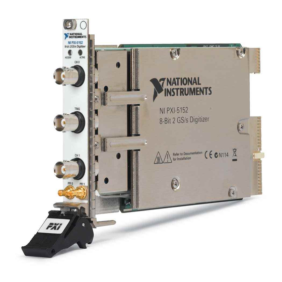
PXI/PCI-5152 Front Panel Connectors and Indicators............................................................. 8
Configuring the PXI/PCI-5152 in MAX...................................................................................9
Programming the PXI/PCI-5152.............................................................................................10
NI-SCOPE Examples...................................................................................................... 11
Making a Measurement...........................................................................................................12
Making a Measurement with NI-SCOPE SFP................................................................ 12
Making a Measurement with LabVIEW......................................................................... 12
Setting Up PXI/PCI-5152 for Synchronization...................................................................... 12
PXI Modules................................................................................................................... 13
PCI Modules................................................................................................................... 13
Troubleshooting...................................................................................................................... 13
Why Is the ACCESS LED Off When the Chassis Is On?...............................................13
What Should I Do if the PXI/PCI-5152 Doesn't Appear in MAX?................................ 14
You can impair the protection provided by the PXI/PCI-5152 if you use it
Advertisement
Table of Contents

Summary of Contents for NI PXI-5152
-
Page 1: Table Of Contents
PXI/PCI-5152 Front Panel Connectors and Indicators............. 8 Configuring the PXI/PCI-5152 in MAX...................9 Programming the PXI/PCI-5152.....................10 NI-SCOPE Examples...................... 11 Making a Measurement......................12 Making a Measurement with NI-SCOPE SFP..............12 Making a Measurement with LabVIEW................. 12 Setting Up PXI/PCI-5152 for Synchronization..............12 PXI Modules........................13 PCI Modules........................13 Troubleshooting........................ -
Page 2: Electromagnetic Compatibility Guidelines
Do not install a device if it appears damaged in any way. Unpack any other items and documentation from the kit. Store the device in the antistatic package when the device is not in use. 2 | ni.com | PXI/PCI-5152 Getting Started Guide... -
Page 3: Kit Contents
(PCI Devices) A desktop computer and its documentation Note If your application uses NI-TClk synchronization for PCI devices, you must use a RTSI cable to connect the PCI devices. For more information, refer to NI High-Speed Digitizers Help»Programming»Reference»NI-TClk Synchronization Help. -
Page 4: Preparing The Environment
For complete specifications, refer to specifications document for your device at ni.com/ manuals. Installing the Software You must be an Administrator to install NI software on your computer. ™ ™ Install an ADE, such as LabVIEW or LabWindows /CVI Insert the driver software media into your computer. -
Page 5: Installing The Pxi-5152
2. PXI Peripheral Slot 5. PXI Express Peripheral Slot 3. PXI Express Hybrid Peripheral Slot PXI-5152 modules can be placed in PXI peripheral slots or PXI Express Hybrid peripheral slots. Touch any metal part of the chassis to discharge static electricity. -
Page 6: Installing The Pci-5152
Locate a compatible slot and remove the corresponding slot cover on the computer back panel. PCI-5152 modules can only be inserted into PCI slots. To maximize airflow and extend the life of the PCI device, leave any adjacent PCI slots empty. 6 | ni.com | PXI/PCI-5152 Getting Started Guide... - Page 7 Touch any metal part of the computer to discharge any static electricity. Insert the module into the slot you selected. Gently rock the module in to place without forcing it. Figure 4. Module Installation 1. Module 2. System Expansion Slot 3.
-
Page 8: Pxi/Pci-5152 Front Panel Connectors And Indicators
CH 0, CH 1 Standard BNC female Analog input connection; digitizes data and connector triggers acquisitions. TRIG Standard BNC female External analog trigger connection; signals on the connector TRIG connector cannot be digitized. 8 | ni.com | PXI/PCI-5152 Getting Started Guide... -
Page 9: Configuring The Pxi/Pci-5152 In Max
Table 2. PXI-5152 Front Panel Indicators Label Function ACCESS Indicates the status of the PCI bus and the interface from the PXI-5152 to the controller. ACTIVE Indicates the status of the onboard acquisition hardware of the PXI-5152. Configuring the PXI/PCI-5152 in MAX Use Measurement &... -
Page 10: Programming The Pxi/Pci-5152
14 Programming the PXI/PCI-5152 You can acquire data interactively using the NI-SCOPE SFP, or you can use the NI-SCOPE instrument driver to program your device in the supported ADE of your choice. 10 | ni.com | PXI/PCI-5152 Getting Started Guide... -
Page 11: Ni-Scope Examples
Examples demonstrate the functionality of the device and serve as programming models and building blocks for your own applications. The NI Example Finder is a utility available for some ADEs that organizes examples into categories and allows you to easily browse and search installed examples. You can see descriptions and compatible hardware models for each example, or see all the examples compatible with one particular hardware model. -
Page 12: Making A Measurement
Click Run to run the example program. Setting Up PXI/PCI-5152 for Synchronization The PXI/PCI-5152 is built on NI Synchronization and Memory Core (SMC) technology and therefore supports TClk synchronization. To synchronize SMC-based devices and share triggers or clocks, you must configure components in MAX. -
Page 13: Pxi Modules
In the dialog box that opens, select NI-RTSI Cable. Click Finish. In the MAX configuration pane, right-click the NI-RTSI cable, select Add Device to NI- RTSI Cable, and select the device you want to add. For more information about connecting PCI devices, refer to NI High-Speed Digitizers Help»... -
Page 14: What Should I Do If The Pxi/Pci-5152 Doesn't Appear In Max
Verify that the module appears in MAX. Reset the module in MAX and perform a self-test. If the ACCESS LED still fails to light and failures continue, contact NI technical support or visit ni.com/support. Related Information Installing the PXI-5152... -
Page 15: Where To Go Next
Related Information Installing the PXI-5152 on page 5 Installing the PCI-5152 on page 6 Where to Go Next Located online at ni.com/manuals Located using the NI Example Finder EXPLORE LEARN CREATE the application development about hardware features custom applications with... -
Page 16: Worldwide Support And Services
. You can find patents.txt ni.com/patents information about end-user license agreements (EULAs) and third-party legal notices in the readme file for your NI product. Refer to the Export Compliance Information at for the NI global trade compliance policy and how ni.com/legal/export-compliance...
Need help?
Do you have a question about the PXI-5152 and is the answer not in the manual?
Questions and answers