
Subscribe to Our Youtube Channel
Summary of Contents for IFM Electronic efector 800 VSE002
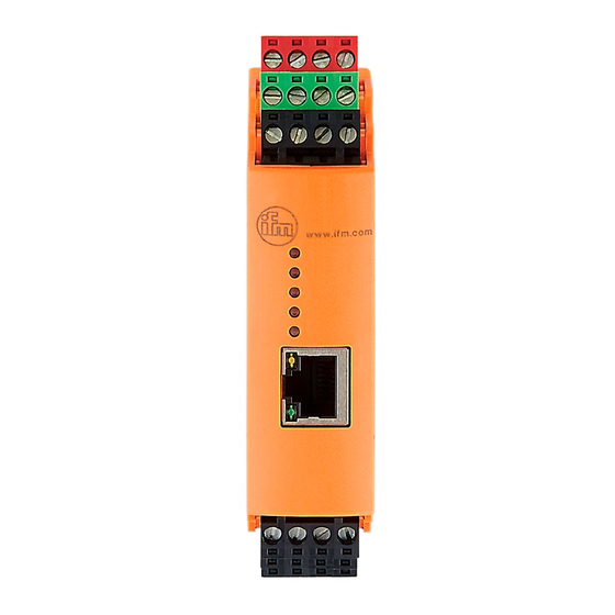
- Page 1 Operating instructions Diagnostic electronics for vibration sensors VSE002 / VXE002 / VXE003 VYE001 / VYE002 / VYE003 / VYE104...
-
Page 2: Table Of Contents
Contents 1 Preliminary note ���������������������������������������������������������������������������������������������������3 2 Safety instructions �����������������������������������������������������������������������������������������������3 3 Functions and features ����������������������������������������������������������������������������������������3 4 Installation������������������������������������������������������������������������������������������������������������5 4�1 Installation of the sensors ������������������������������������������������������������������������������5 5 Electrical connection ��������������������������������������������������������������������������������������������5 5�1 Limited voltage / current ��������������������������������������������������������������������������������6 5�2 Wiring�������������������������������������������������������������������������������������������������������������6 5�2�1 Wiring of the sensors 1���4 (S1���S4) according to the sensor ��������������7 5�3 Connection of the sensors �����������������������������������������������������������������������������7 5�3�1 Monitoring the sensor cable �����������������������������������������������������������������7 5�4 Ethernet connection ���������������������������������������������������������������������������������������8... -
Page 3: Preliminary Note
1 Preliminary note • An instruction is indicated by "►": Example: ► Mount the unit as shown. Important note Non-compliance may result in malfunction or interference� Information Supplementary note 2 Safety instructions • Please read the operating instructions prior to set-up of the unit� Ensure that the product is suitable for your application without any restrictions�... - Page 4 • An analogue current signal can also be connected to the dynamic inputs to monitor max� 4 more process values� Moreover up to 4 vibration sensors from ifm (types VSA, VSP) or sensors with an IEPE standard signal can be connected� •...
-
Page 5: Installation
The device is not approved for safety-related tasks in the field of operator protection� 4 Installation Mount the unit in a control cabinet with a protection rating of at least IP 54 to ensure protection against accidental contact with dangerous contact voltages and against atmospheric influence�... -
Page 6: 5�1 Limited Voltage / Current
• connector with screw terminals, order no� E40173 The outputs are short-circuit proof up to 100 mA� The outputs can be configured as either normally closed or normally open� In addition an analogue signal can be provided on output [OU 1] (0/4���20 mA) (e�g�... -
Page 7: 5�2�1 Wiring Of The Sensors 1
Terminal Connection Description IN 2 Process value input 2 GND 2 5.2.1 Wiring of the sensors 1...4 (S1...S4) according to the sensor Sensor input Usage IEPE 0���20 mA Do not use Do not use Do not use Sensor supply 9 V IEPE Current input Current input 0���10... -
Page 8: 5�4 Ethernet Connection
• the output [OU 2] clocks at 1 Hz • the [SENS] LED flashes green 5.4 Ethernet connection The RJ45 socket is used for the connection to the Ethernet� Ethernet cables can be supplied as accessories, e.g.: cross-over cable, 2 m, article no� EC2080 cross-over cable, 5 m, article no�... -
Page 9: Indicators (Leds)
7 Indicators (LEDs) LED 1 for sensor 1 Lights green Sensor connected and configured Flashes green Sensor is configured; LED 1 type VSA LED 2 sensor is not connected LED 3 or faulty LED 4 type IEPE sensor not LED 5 connected Lights yellow Early warning... -
Page 10: Maintenance, Repair And Disposal
8 Maintenance, repair and disposal If used correctly, no maintenance and repair measures are necessary� Only the manufacturer is allowed to repair the unit� After use dispose of the unit in an environmentally friendly way in accordance with the applicable national regulations�...
Need help?
Do you have a question about the efector 800 VSE002 and is the answer not in the manual?
Questions and answers