
Related Manuals for MasterCraft 055-6745-2

Summary of Contents for MasterCraft 055-6745-2
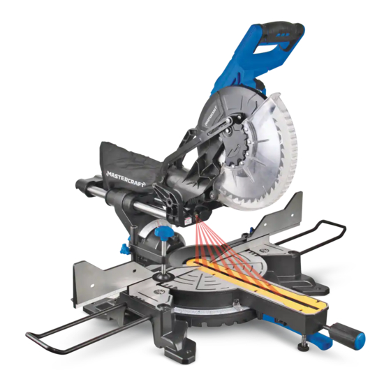
- Page 1 055-6745-2 DUAL-BEVEL SLIDING COMPOUND MITRE SAW WITH LASER LINE INSTRUCTION IMPORTANT: MANUAL Please read this manual carefully before using this mitre saw and save it for reference...
-
Page 2: Table Of Contents
TABLE OF CONTENTS SPECIFICATIONS SAFETY GUIDELINES KEY PARTS DIAGRAM ASSEMbLY AND ADJUSTMENTS OPERATING INSTRUCTIONS MAINTENANCE TROUbLESHOOTING ExPLODED VIEW PARTS LIST WARRANTY NOTE: If any parts are missing or damaged, or if you have any questions, please call our toll-free helpline at 1-800-689-9928. -
Page 3: Specifications
055-6745-2 | contact us 1-800-689-9928 SPECIFICATIONS SAFETY GUIDELINES Motor 120V AC, 60 Hz, 15A • Keep guards in place and in working order. Speed 5000 RPM (no load) • Remove adjusting keys and wrenches. Form habit of checking to see that keys and adjusting blade 10”... - Page 4 055-6745-2 | contact us 1-800-689-9928 • Never stand on tool. Serious injury could occur if the tool is tipped or if something unintentionally • Avoid body contact with grounded surfaces such as pipes, radiators, ranges and refrigerators. There is an increased risk of electric shock if your body is grounded.
- Page 5 055-6745-2 | contact us 1-800-689-9928 • The laser beam can be harmful to the eyes. Always avoid direct eye exposure. Do not project the • Always make sure that the mitre table and head assembly (bevel function) are locked in laser beam directly into the eyes of others or at any object other than the workpiece.
- Page 6 055-6745-2 | contact us 1-800-689-9928 • Keep the motor air slots clean and free of chips or dust. To avoid motor damage, the motor • Crosscut: A cutting operation made across the grain of the workpiece. should be blown out or vacuumed frequently. This keeps sawdust from interfering with the motor •...
- Page 7 055-6745-2 | contact us 1-800-689-9928 Description Description Description Description Switch handle Positive mitre stop Dust bag Bevel lock knob On/Off trigger switch Mounting hole Blade Bevel scale Upper blade guard Motor Handhold for transportation Table Lower blade guard...
- Page 8 055-6745-2 | contact us 1-800-689-9928 REMOVING AND INSTALLING THE BLADE with the arrow on the upper blade guard. Make sure that the blade teeth are pointing downward. Removing blade (Fig. 1 to 4) • Place the out flange against the blade and on the arbor.
- Page 9 055-6745-2 | contact us 1-800-689-9928 INSTALLING THE DUST BAG Mitre Angle Pointer Adjustment (Fig. 5) (Fig. 6) • Squeeze the metal collar wings on the dust bag. • Move the table to the 0° positive stop. 。 •...
- Page 10 055-6745-2 | contact us 1-800-689-9928 90° (0°) Bevel Adjustment (Fig. 8) • Tilt the cutting arm to the left to 45° bevel and recheck for alignment. • Repeat above steps until the blade is at 45° to the table.
- Page 11 055-6745-2 | contact us 1-800-689-9928 UNLOCKING AND LOCKING THE CUTTING BENCH MOUNTING (Fig. 14) HEAD (Fig. 12) This tool should be bolted with four bolts to a level and stable surface using the bolt holes (1) provided in the tool’s To unlock: Press and lightly hold down the cutting head.
- Page 12 055-6745-2 | contact us 1-800-689-9928 COMPOUND CUT • Clamp the workpiece with the work clamp if (Fig. 20) necessary. A compound cut is the combination of a mitre and a bevel Follow all of the cutting instructions for the type of cut to cut simultaneously.
- Page 13 055-6745-2 | contact us 1-800-689-9928 SLIDE CUTTING WIDE BOARDS UP TO 12” (30.5 cm) WIDE the stop knob until the cutting head down until the teeth of the blade are at the desired depth. To avoid injury: •...
- Page 14 055-6745-2 | contact us 1-800-689-9928 Bevel/Mitre Settings (when the angle between the walls equals 90°) wood fence can be mounted to your saw. Holes are provided in the saw fence to attach an auxiliary wood fence (this provides additional depth of cut). This fence should be constructed of straight auxiliary wood approximately 3/4”...
- Page 15 055-6745-2 | contact us 1-800-689-9928 CROWN MOULDING CHART 52/38° CROWN MOULDING 45/45° CROWN MOULDING To aid in the correct setting, the compound angle setting chart below has been Angle Between Mitre Setting Bevel Setting Mitre Setting Bevel Setting provided.
- Page 16 055-6745-2 | contact us 1-800-689-9928 SAWDUST 52/38° CROWN MOULDING 45/45° CROWN MOULDING Periodically, sawdust will accumulate under the table and base. This could cause difficulty in the movement Angle Between of the table when setting up a mitre cut. Frequently blow out or vacuum up the sawdust.
-
Page 17: Assembly And Adjustments
055-6745-2 | contact us 1-800-689-9928 LUBRICATION (Fig. 32) SUGGESTED COrrECTIVE PrOBLEM PrOBABLE CAUSE ACTION All the motor bearings in this tool are lubricated with a sufficient amount of high-grade lubricant for the life of Motor brushes not sealed or lightly the unit under normal operating conditions;... - Page 18 055-6745-2 | contact us 1-800-689-9928 MASTERCRAFT 10” (25.4 CM) DUAL-BEVEL SLIDING COMPOUND MITRE SAW ® When servicing the Mastercraft ® Dual-bevel Sliding Compound Mitre Saw with Laser Line, use only Mastercraft replacement parts. The use of any other parts may cause damage to the product. All servicing ®...
- Page 19 055-6745-2 | contact us 1-800-689-9928 Description Description Description Description Dust connection tube Spring washer Hexagon screw Screw Fixed guard Screw Sliding support cover Stop plate Bearing Clamp rod Buffer ring Wave washer Brand label Mitre pointer Sliding lock knob...
-
Page 20: Warranty
3-Year Limited Warranty Additional Limitations This Mastercraft product is guaranteed for a period of 3 years from the date of original retail purchase This warranty applies only to the original purchaser and may not be transferred. Neither the retailer nor...
Need help?
Do you have a question about the 055-6745-2 and is the answer not in the manual?
Questions and answers
how do you adjust the laser light on the saw model # 055-6745-2
The manual does not provide specific instructions for adjusting the laser light on the MasterCraft saw model # 055-6745-2. However, it states that the laser light assembly should not be replaced with a different one and that any repairs must be carried out by the manufacturer or an authorized service agent. Additionally, it advises against attempting to repair or change any parts of the laser guide yourself.
This answer is automatically generated