Blodgett DFG-50 Installation Operation & Maintenance
Hide thumbs
Also See for DFG-50:
- Installation and operation manual (205 pages) ,
- Installation operation & maintenance (91 pages) ,
- Installation, operation and maintenance manual (90 pages)
Table of Contents
Advertisement
Quick Links
Advertisement
Table of Contents

Subscribe to Our Youtube Channel
Related Manuals for Blodgett DFG-50


Summary of Contents for Blodgett DFG-50
- Page 1 DFG-50 CONVECTION OVEN INSTALLATION - OPERATION - MAINTENANCE BLODGETT OVEN COMPANY www.blodgett.com 44 Lakeside Avenue, Burlington, Vermont 05401 USA Telephone: (802) 658-6600 Fax: (802)864-0183 PN 17355 Rev T (3/14) © 2014 - G.S. Blodgett Corporation...
- Page 2 Your Service Agency’s Address: Model Serial number Oven installed by Installation checked by...
-
Page 3: Table Of Contents
Blodgett IQ2™ Vision Control ........ -
Page 4: Installation
Oven Description and Specifications Cooking in a convection oven differs from cooking in a Blodgett convection ovens represent the latest advance- conventional deck or range oven since heated air is con- ment in energy efficiency, reliability, and ease of opera- stantly recirculated over the product by a fan in an en- tion. -
Page 5: Delivery And Location
DELIVERY AND INSPECTION It is essential that an adequate air supply to the oven be maintained to provide a sufficient flow of combustion and All Blodgett ovens are shipped in containers to prevent ventilation air. damage. Upon delivery of your new oven: •... -
Page 6: Stand Assembly
Installation Stand Assembly STAND OPTIONS Stands With Shelves Small Stands Without Shelves 1. Place stand frame upside down on a work surface. • The 5-3/4” (15cm) stand is used for a single oven, 2. Attach one leg to each of the corner stud bolts on the when short legs are required for countertop use. - Page 7 Installation Stand Assembly Open Stands With Shelves and Racks 1. Place stand frame upside down on a work surface. 7. Insert a carriage bolt from the outside of the leg, through the leg, and through the shelf corner bracket. 2. Attach one leg to each of the corner stud bolts on the bottom of the stand top.
-
Page 8: Oven Assembly
Installation Oven Assembly OVEN ASSEMBLY TO STAND Single Section Double Section 1. Place the assembled stand in the location where the 1. Assemble the lower section to the stand as described. oven is going to be used. DO NOT replace the side control compartment or close the front control panel. -
Page 9: 4" (10Cm) Leg Attachment
Installation Oven Assembly 4” (10CM) LEG ATTAChMENT CASTER INSTALLATION 1. Lay the oven on its side. NOTE: Casters are not supplied for the 4” (10cm) legs, 5-3/4” (15cm) or 7” (18cm) stands. 2. Screw one leg into each of the corner nuts. NOTE: Install the locking casters on the front of the oven. -
Page 10: Ventilation
Installation must conform with Local and National instal- lation standards. Local installation codes and/or require- ments may vary. If you have any questions regarding the proper installation and/or operation of your Blodgett oven, please contact your local distributor. If you do not have a Draft Diverter local distributor, please call the Blodgett Oven Company at 0011-802-658-6600. - Page 11 Installation Ventilation DIRECT FLUE ARRANGEMENT Installing the draft hood When the installation of a mechanically driven exhaust Ovens ordered for direct venting are supplied with a draft hood is impractical the oven may be vented by a direct hood. Install the draft hood as follows: flue arrangement.
-
Page 12: Posted In A Prominent Lo- Utility Connections - Standards And Codes
Local installation codes and/or require- tric appliance. ments may vary. If you have any questions regarding the proper installation and/or operation of your Blodgett oven, Qualified installation personnel must be experienced in please contact your local distributor. If you do not have a... -
Page 13: Gas Connection
NOTE: BTU values in the following example are for natu- 1460 2750 ral gas. 1180 2200 You purchase a DFG-50 to add to your existing cook line. 1900 1. Add the BTU rating of your current appliances. 1680 Pitco Fryer 120,000 BTU... -
Page 14: Pressure Regulation And Testing
Each oven is supplied with a regulator to maintain the proper gas pressure. The regulator is essential to the DFG-50 ovens are rated at 27,500 BTU/Hr. (8.1 kW) (29 proper operation of the oven and should not be re- MJ) or 34,500 BTU/Hr. (10.1 kW) (36 MJ) per section. -
Page 15: Gas Hose Restraint
1. A 3/8” diameter hole has been provided on the bottom tion of your Blodgett oven, please contact your local dis- of the oven just below the gas inlet. the hole is sized tributor. -
Page 16: Electrical Connection
DO NOT cut or remove the ground- The Blodgett Oven Company cannot assume respon- ing prong from this plug. sibility for loss or damage suffered as a result of im- proper installation. -
Page 17: Initial Startup
Installation Initial Startup The following is a check-list to be completed by qualified ADjUSTMENTS ASSOCIATED WITh INITIAL INSTAL- personnel prior to turning on the appliance for the first LATION time. Each oven, and its component parts, have been thorough- 1. Open the manual shut-off valve at the rear of the ly tested and inspected prior to shipment. -
Page 18: Operation
DO NOT use tools to turn off the gas control. If the erating instructions. They are the key to the successful gas cannot be turned off manually do not try to re- operation of your Blodgett oven. pair it. Call a qualified service technician. SAFETY TIPS •... -
Page 19: Solid State Manual Control
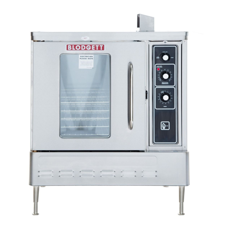
Operation Solid State Manual Control CONTROL DESCRIPTION 1. SELECTOR SWITCH - controls power to the oven for cook or cool down. 2. OVEN READY LIGHT - when lit indicates burner op- eration. When the light goes out the oven has reached operating temperature. -
Page 20: The Information Contained In This Solid State Digital Control
Operation Solid State Digital Control CONTROL DESCRIPTION 1. SELECTOR SWITCH - turns power to the oven on or off. Allows selection of Cook or Cool Down Modes. 2. DISPLAY - displays time or temperature and other in- formation related to oven function. 3. - Page 21 Operation Solid State Digital Control OPERATION Cook with Pulse: Cook Only: NOTE: PULSE light is on when pulse mode is on and off when pulse mode is off. 1. Turn SELECTOR switch (1) to the desired position. 1. Turn the SELECTOR SWITCH (1) to the desired posi- 2.
-
Page 22: Manual Is Important For The Prop-Ch-Pro3 (Solid State Programmable Digital Control)
Operation Ch-Pro3 (Solid State Programmable Digital Control) COMPONENT DESCRIPTION 1. SELECTOR SWITCH - turns power to the oven on or off. Allows selection of cook or cool down modes and Solid State fan speed (if applicable). 2. TIME DISPLAY - gives cook time. 3. - Page 23 Operation Ch-Pro3 (Solid State Programmable Digital Control) MANUAL OPERATION NOTE: Press the arrow keys to change the cook time and 8. When the cook time expires both displays flash and temperature at any point duringmanual operation. an audible alarm sounds for several seconds then self cancels.
- Page 24 Operation Ch-Pro3 (Solid State Programmable Digital Control) PROGRAMMING ThE MANUAL kEY DEFAULT PROGRAMMING ThE PRODUCT kEYS 1. Turn the SELECTOR SWITCH (1) to the desired posi- 1. Turn the SELECTOR SWITCH (1) to the desired posi- tion. tion. 2. Press the MANUAL KEY (12). The manual and fan 2.
-
Page 25: Blodgett Iq2™ Vision Control
Operation Blodgett IQ2™ Vision Control COMPONENT DESCRIPTION 1. OVEN POWER SWITCH - controls power to the oven. 2. DISPLAY - displays temperature and other controller related information. 3. PROGRAM KEY - press to enter the programming mode. 4. PROGRAM ARROW KEYS - use to move through programming menus and options 5. - Page 26 Operation Blodgett IQ2™ Vision Control OVEN OPERATION Oven Startup: three seconds to cancel the cook cycle for normal operation. To cancel the cook cycle 1. Toggle the POWER SWITCH (1) to ON. The display when using shelf timing, press and hold the gives the software revision level.
- Page 27 Operation Blodgett IQ2™ Vision Control 2. Load the product into the oven. Press the desired 6. Press the SHELF KEY (16) for the finished product PRODUCT KEY (14). to silence the alarm. Remove the product. Close the oven door. The DISPLAY (2) scrolls the product name...
- Page 28 Operation Blodgett IQ2™ Vision Control PRODUCT kEY PROGRAMMING To enter the product programming mode To program the product 1. Press and hold the PROGRAM KEY (3). The DIS- 4. The display reads: PLAY (2) reads: Shelf Cook Prod Cnt Programming...
- Page 29 Operation Blodgett IQ2™ Vision Control 7. The display reads: Use the PRODUCT KEYS (14) to enter the desired length of the time the fan should be on in the pulse cycle. Press PROGRAM KEY (3). The display reads: Stage 1 Timing...
- Page 30 Operation Blodgett IQ2™ Vision Control 14. The display reads: Alarm 1 Name Hold Done To change the alarm name, use the PROGRAM AR- ROW KEYS (4) to scroll through the alarm name li- Use the PROGRAM ARROW KEYS (4) to select ei- brary.
- Page 31 Operation Blodgett IQ2™ Vision Control SYSTEM LEVEL PROGRAMMING 3. The display reads: Entering the system programming mode 1. Press and hold the PROGRAM KEY (3). The display Tone Volume reads: Product Cnt Use the PROGRAM ARROW KEYS (4) to select Programming None, 1, 2, 3 or 4.
- Page 32 Operation Blodgett IQ2™ Vision Control This enables you to program a product name. Use Definition: If you are using sensitivity as a tim- the PROGRAM ARROW KEYS (4) to select either ing mode for single stage stage recipes this Yes or No. Press the PROGRAM KEY (3).
- Page 33 Operation Blodgett IQ2™ Vision Control 17. The display reads: 2. Use the up and down PROGRAM ARROW KEYS (4) to scroll through the existing product names. Or press the PRODUCT KEY (14) that corresponds with the Recipe Timing first letter of the name you are looking for. Then use the PROGRAM ARROW KEYS (4) to scroll to the de- sired name.
- Page 34 Operation Blodgett IQ2™ Vision Control Use the PROGRAM ARROW KEYS (4) to select ei- Programming the ALARM NAME ther ADD, MODIFY or CANCEL. Select ADD to cre- NOTE: Use these instructions to modify an existing ate a new alarm name. Select MODIFY to change an name, to add an alarm name or to delete a name existing alarm name.
-
Page 35: To These Procedures And Instruc-How Cook & Hold Works
Operation how Cook & hold Works With the optional COOK & HOLD feature, meat is roasted at lower temperatures for longer periods of time. This pre- Oven switches from cook to hold serves flavor and tenderness and prevents over drying. There are three phases in cook and hold roasting. -
Page 36: Tions Will Result In Satisfactory General Guidelines For Operating Personnel
Operation General Guidelines for Operating Personnel COOk TIMES AND TEMPERATURES OPERATING TIPS Preheating the oven Pans and Racks Always preheat the oven before baking or roasting. We Product or pan height determines how many racks are recommend preheating 50°F (28°C) above the cook tem- used. -
Page 37: Suggested Times And Temperatures
Operation Suggested Times and Temperatures PRODUCT TEMPERATURE TIME # ShELVES Meats Hamburger Patties (5 per lb) 400°F (205°C) 8-10 mins. Steamship Round (80 lb. quartered) 275°F (135°C) 2 hrs 45 mins. Standing Rib Choice (20 lbs, trimmed, rare) 235°F (115°C) 2 hrs 45 mins. -
Page 38: Maintenance
Heat tint and heavy discoloration If maintenance or repairs are required, contact your local may be removed with any non-toxic commercial oven Blodgett service company, a factory representative or the cleaner. Blodgett Oven company. 1. Apply cleaners when the oven is cold. Always rub with the grain of the metal. -
Page 39: Troubleshooting Guide
*Denotes remedy is a difficult operation and should be performed by qualified personnel only. It is recommended, how- ever, that All repairs and/or adjustments be done by your local Blodgett service agency and not by the owner/operator. Blodgett cannot assume responsibility for damage as a result of servicing done by unqualified personnel.
Need help?
Do you have a question about the DFG-50 and is the answer not in the manual?
Questions and answers