Table of Contents
Advertisement
Advertisement
Table of Contents

Summary of Contents for Schlage HandPunch 2000
- Page 1 HP-2000 Terminal User’s Guide...
- Page 2 Schlage Biometrics, Inc. reserves the right to change, without notice, product offerings or specifications. No part of this publication may be reproduced in any form without the express written permission from Schlage Biometrics, Inc.
-
Page 3: Table Of Contents
Table of Contents Introduction Biometrics Principle of Operation Specifications Planning an Installation Site Preparation HandPunch Placement Wiring Power Input Battery Backup Operation HandPunch to Host Computer Connection RS-232 Host Computer Connection Modem Host Computer Connection Mechanical Installation Wall Plate Installation Wiring Connections Erasing the Memory Closing the HandPunch... -
Page 5: Introduction
1 For the sake of using a consistent name throughout the manual, the HandPunch 2000 terminal is referred to as the HandPunch for the remainder of this manual. -
Page 6: Principle Of Operation
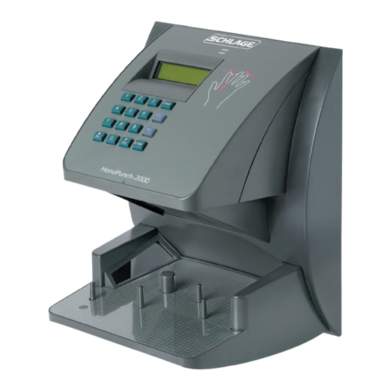
Introduction Principle of The HandPunch uses low-level infrared light, optics, and a CMOS (IC chip) camera to capture a three-dimensional image of the hand. Using advanced microprocessor Operation technology, the HandPunch converts the image to an electronic template. It stores the template in a database with the user’s ID number. - Page 7 HandPunch 2000 Manual HAND PLACEMENT DISPLAY VERIFICATION LIGHTS LCD DISPLAY NUMERICAL KEYPAD FUNCTION KEYS PLATEN AND GUIDE PINS Figure 1-1: The HandPunch 2000...
-
Page 8: Specifications
Introduction Specifications Table 1: Specifications Size: 8.85 inches wide by 11.65 inches high by 8.55 inches deep 22.3 cm wide by 29.6 cm high by 21.7 cm deep Power: 12 to 24 VDC or 12 to 24 VAC 50-60 Hz, 7 watts Weight: 6 lbs (2.7 kg) –... - Page 9 HandPunch 2000 Manual Options The HandPunch has the following options available. See Technical Note 70200-0012 rev C • Backup Battery Support See Technical Note 70200-0013 rev C • Modem Communication Hand Readers are UL Listed as stand alone units only (i.e. the card reader function UL Compliance has not been evaluated by UL).
- Page 10 Introduction This page is intentionally blank.
-
Page 11: Planning An Installation
40 in. (102 cm.) Figure 2-1: HandPunch Placement Rules NOTE For the following sections, Schlage Biometrics does not supply hardware items such as power or communications wiring. -
Page 12: Wiring
Planning an Installation Wiring Two basic circuits typically connect to the HandPunch: • Power Input • HandPunch to Host Computer - RS-232 - modem The minimum wire size for these circuits is AWG 22; the maximum is AWG 18. Power Input The HandPunch uses an internal switching regulator to obtain internal operational power. -
Page 13: Handpunch To Host Computer Connection
HandPunch 2000 Manual Additional options installed and specific configurations within the HandPunch make it difficult to predict precisely how long battery support will last, but in general two hours of battery operation can be expected. While operating on battery backup due to loss of main input power, the battery output voltage is constantly monitored by internal circuitry. -
Page 14: Modem Host Computer Connection
Planning an Installation Modem Host The HandPunch is also available with an optional modem module for telephone line communications between the HandPunch network and the host computer. When Computer connecting via modem, one HandPunch terminal must be configured with the modem Connection option. -
Page 15: Mechanical Installation
Mechanical Installation Select an installation location based on the guidelines provided in the Planning an Installation section beginning on page page 9. Wall Plate Installation Wall Preparation For the following procedure protect the HandPunch from the dust and debris generated NOTE during the wall plate installation process. - Page 16 Mechanical Installation 5. Align a bubble level with the top edge of the wall plate and gently rotate the wall plate until the bubble level shows that the top edge of the wall plate is level. 6. Secure the plate to the wall using heavy masking tape. 7.
- Page 17 HandPunch 2000 Manual Wall Plate SURFACE CONDUIT ENTRY POINT 50" Reference (127 cm) to Top of Wall Plate 42.75" (108.6 cm) 42.5" HandPunch (108 cm) Finished Floor Figure 3-2: HandPunch Wire Routing Layout NOTE Dust and debris surrounding the HandPunch can drastically affect the terminal’s operation.
- Page 18 Mechanical Installation HOLE 2 UPPER SCREWS SURFACE CONDUIT ENTRY REAR OF TERMINAL Figure 3-3: Attaching the HandPunch to the Wall Plate...
-
Page 19: Wiring Connections
Wiring Connections Once the HandPunch is attached to the wall plate the wiring connections to the HandPunch can be made (see Figure 4-1). J7 Battery Reset WALL Wall Plate Jumper Switch Power Top of Optional Modem Connectors Serial RS-232 Terminal Top of HandPunch Figure 4-1: Board Layout Wiring... - Page 20 Wiring Connections Table 2: RS-232 Serial Connection J8 Pin Signal Connection Ground Receive Data Input (from external device) Transmit Data Output (to external device) Ready to Send Output (to external device) RS-232 Pins Figure 4-2: J4 - RS-232 Jack Pinout...
- Page 21 HandPunch 2000 Manual Connection HandPunch to Host Serial Cable Serial Port Computer RS-232 Serial Unit Host Computer Figure 4-3: Host PC to RS-232 Connection HandPunch RJ-11 RJ-11 RSI Supplied Cable (Black) Jack Modem Port Modem Unit RJ-11 Telephone Outlet Figure 4-4: Host PC to HandPunch Modem Connection...
-
Page 22: Erasing The Memory
Erasing the Memory There are two options when erasing the memory of the HandPunch. 1. Setup 2. All The erasing of the setup will set the HandPunch’s address, passwords, etc. back to factory defaults. Choosing the All option will take the HandPunch’s setup back to factory defaults plus erase all user databases and datalogs. -
Page 23: Closing The Handpunch
Closing the HandPunch Before closing the HandPunch clear all dust and debris away from the HandPunch. With the wall mount latch in the unlocked position, swing the body of the HandPunch up and lock the latch into place with the key provided with the HandPunch (see Figure 6-1). NOTE Dust and debris surrounding the HandPunch can drastically affect the terminal’s operation. -
Page 24: Enter Command Menu
Enter Command Menu Press the CLEAR ENTER keys simultaneously to enter a command menu. If No One is 1. The display appears as follows. Enrolled in the HandPunch ENTER PASSWORD 2. Press the default password for the menu you wish to enter. Press for the Service Menu. - Page 25 HandPunch 2000 Manual ENTER PASSWORD 4. Enter the password for the menu you wish to enter. The default passwords are as follows. Press for the Service Menu. Press for the Setup Menu. Press for the Management Menu. Press for the Enrollment Menu.
-
Page 26: Navigating Command Menus
Enter Command Menu Navigating Once you have entered a command menu, there are three options available for navigating Command the command menu system. Menus 1. Press to enter the command shown on the display. 2. Press to step to the next command in the menu. 3. - Page 27 This page is intentionally blank...
-
Page 28: Programming The Handpunch
The default menu passwords are given in Table 3. To increase the security of the HandPunch, Schlage Biometrics recommends changing the passwords for the command menus to new numbers. These password numbers can be up to 10 digits long. - Page 29 Add Supervisor (designated as a supervisor), all further user authority levels are assigned. The first person enrolled should be enrolled using the Add Supervisor command. This protects the integrity of the system. Schlage Biometrics strongly recommends enrolling at least two users as supervisors to ensure that more than one person has the authority to access all menus and all commands.
- Page 30 Programming the HandPunch System Management Once a HandPunch system is in operation the following commands are used for system management. List Users – List the Users authorized to use a HandPunch. This is done through the Management Menu. The instructions for listing employees begin on page page 35. Set User Data –...
-
Page 31: Service Menu
HandPunch 2000 Manual Service Menu The Service menu commands provide information that help you determine if the HandPunch is performing within normal operating parameters and identify the status of the unit’s inputs and outputs. The following section provides a brief summary of the Service Menu commands. - Page 32 Aux Out 1 * Aux Out 0 These Input/Output * Lock values do not apply to Aux In 2 the HandPunch 2000 Request to Exit Aux In 1 Door Monitor Switch Tamper * These status values are inactive if the reader is in Card Reader Output Mode.
-
Page 33: Setup Menu
HandPunch 2000 Manual Setup Menu The Setup menu commands allow you to set the basic operating parameters for the HandPunch unit. The following section provides a brief summary of all the parameters that may be set on a HandPunch unit. - Page 34 Programming the HandPunch Table 6: Setup Command Menu Setup Menu Password = 2 Set Language Select Language Set Date Format Select Date Format Set Time and Date Month (MM) Day (DD) Year (YY) Hour (HH) Minute (MM) Set Address New Address Set ID Length New ID Length Set T &...
- Page 35 HandPunch 2000 Manual Set Language The Set Language command allows the language shown on the HandPunch’s display to be “localized” for a variety of countries. - English - German - Japanese - Russian - French - Indonesian - Italian - Portuguese...
-
Page 36: Management Menu
Programming the HandPunch Management Menu The Management menu commands allow you to manage employee data stored in a HandPunch unit. The following section provides a brief summary of the employee data that may be manipulated on a HandPunch unit. Navigating Enter the appropriate password to enter the Setup command menu. - Page 37 HandPunch 2000 Manual List Users The List Users command allows you to display or print a list of all the employees enrolled in a HandPunch. Set User Data The Set User Data command allows you to set an employee’s Reject Threshold, adjusting the hand read threshold for one employee without affecting the threshold of other employees.
-
Page 38: Enrollment Menu
This protects the integrity of the system by enacting the Authority Level rules described above. Schlage Biometrics strongly recommends enrolling at least two users as supervisors to ensure that more than one person has the authority to access all menus and all commands. - Page 39 • If you enroll people using the last four digits of their phone numbers or social security numbers, you may get duplicate numbers. • If you are enrolling large groups of people you may consider using an enrollment trainer. It is a replica of a platen that is available through your Schlage Biometrics reseller. User Education The HandPunch is easy to use and non-threatening.
- Page 40 Programming the HandPunch Left Hand Some right hands cannot be used in the HandPunch due to disabilities such as missing fingers. You can enroll a user with the left hand facing palm side up. The techniques for Enrollment left hand enrollment are the same as for standard enrollment. The user should keep the back of the hand flat against the platen and move the fingers against the web pin and the finger pins in the same manner as in standard enrollment.
- Page 41 HandPunch 2000 Manual Enrollment There are three commands available from the Enrollment command menu. Commands • Add Employee • Add Supervisor • Remove User Refer to “Table 12” to identify the command you need to perform. Step through all previous commands until you reach the desired command.
-
Page 42: Special Menu
Programming the HandPunch Special Menu The Special menu has one command – Special Enroll. This command accommodates users with disabilities that make it difficult or impossible to use a HandPunch in its standard way. The following section provides a brief description of the Special Menu command. - Page 43 HandPunch 2000 Manual This page intentionally left blank...
-
Page 44: Handpunch Maintenance
HandPunch Maintenance A minimum amount of system maintenance is required to keep HandPunchs fully functional. HandPunchs should be cleaned periodically to prevent an accumulation of dust from affecting the HandPunch’s readability. User Scores should be reviewed periodically to ensure the HandPunch is performing properly. There are NO user serviceable parts inside the HandPunch. - Page 45 HandPunch 2000 Manual User Score Periodically check users’ scores (refer to the Read Score section on page page 38). Scores should average under 30. Occasionally a user will score above 30. This is not necessarily an indication of poor performance. If a number of scores average over 30, clean the HandPunch and check scores again.
-
Page 46: Appendix A -Tips For A Successful Installation
Appendix A - Tips Appendix A Tips for a successful Installation HandPunch • Think of the HandPunch as a camera • Clean the HandPunch before it gets dirty • Use non-abrasive cleaners such as glass cleaners and non-abrasive and clean cloths •... -
Page 47: Appendix B -Noted Board Configuration Differences
HandPunch 2000 Manual Appendix B Noted Board Configuration Differences Because of Schlage Biometrics’ camera retrofit of the HandPunch some changes have been made to the main PCB and they are listed as follows: • Dipswitches have been removed - memory is reset with a push-button reset and user interface with keypad and LCD •... -
Page 48: Appendix C -Mechanical Installation
Appendix C - Mechanical Installation Appendix C Mechanical Installation Select an installation location based on the guidelines provided in the Planning an Installation section beginning on page page 9. Wall Plate Installation Wall Preparation NOTE For the following procedure protect the HandPunch from the dust and debris generated during the wall plate installation process. - Page 49 HandPunch 200 Manual 5. Align a bubble level with the top edge of the wall plate and gently rotate the wall plate until the bubble level shows that the top edge of the wall plate is level. 6. Secure the plate to the wall using heavy masking tape. 7.
- Page 50 Appendix C - Mechanical Installation Wall Plate SURFACE CONDUIT ENTRY POINT 50" Reference (127 cm) to Top of Wall Plate 42.75" (108.6 cm) 42.5" HandPunch (108 cm) Finished Floor Figure 12-2: HandPunch Wire Routing Layout NOTE Dust and debris surrounding the HandPunch can drastically affect the terminal’s operation.
- Page 51 HandPunch 200 Manual LEVELING HOLE 2 UPPER SCREWS SURFACE CONDUIT ENTRY KEYHOLE HOLES 3 LOWER MOUNTING SCREWS REAR OF TERMINAL Figure 12-3: Attaching the HandPunch to the Wall Plate...
- Page 52 Appendix C - Mechanical Installation Wiring Connections Once the HandPunch is attached to the wall plate the wiring connections to the HandPunch can be made (see Figure 12-4). J7 Battery Wall Plate WALL Jumper Top of Serial RS-232 Terminal Power Optional Modem RJ-45 Jack Connectors...
- Page 53 HandPunch 200 Manual Table 10: RJ-45/RS232 Serial Connection J8 Pin Signal Connection - not used - - not used - - not used - Ground Rx Data Receive Data Input (from external device) Tx Data Transmit Data Output (to external device) - not used - - not used - J4 Pins...
- Page 54 Appendix C - Mechanical Installation HandPunch Connection Connection RJ-45 to Serial to Host Serial Port Serial Cable Converter Computer RS-232 Serial Unit Host Computer Figure 12-6: Host PC to HandPunch Modem Connection HandPunch RJ-11 RJ-11 RSI Supplied Cable (Black) Jack Modem Port Modem Unit RJ-11 Telephone Outlet...
- Page 55 HandPunch 200 Manual Setting the DIP Switches The DIP Switch settings perform three tasks for the HandPunch (see Figure 12-8). • Set End of Line (EOL) Termination to match the type of termination needed by the network. • Set the Communication Method to match the type of network used. •...
- Page 56 Appendix C - Mechanical Installation End of Line Termination helps to ensure clean data signals are transmitted through the network wiring. Termination is applied to the end-of-line (EOL) HandPunch in the network daisy- Termination chain. The factory default setting is for EOL termination to be disabled – switches 1 and 2 OFF.
- Page 57 HandPunch 200 Manual Erasing the Perform the following steps to erase both the configuration data and the user database. HandPunch Setup and User 1. With system power OFF, set both switches 4 and 5 ON. Database 2. Turn system power ON and wait 5 seconds. 3.
- Page 58 Appendix C - Mechanical Installation Closing the HandPunch Before closing the HandPunch, ensure dip switches 4 and 5 are OFF (refer to Figure 12-8 on page page 53). Clear all dust and debris away from the HandPunch. With the wall mount latch in the unlocked position, swing the body of the HandPunch up and lock the latch into place with the key provided with the HandPunch (see Figure 12-9).
-
Page 59: Appendix D -Troubleshooting Guide
HandPunch 2000 Manual Appendix D Troubleshooting Guide Display Messages During Verification Various messages can appear on the HandPunch’s display during hand verification. These messages are defined in Table 11. Table 11: Display Messages During Verification Message Definition PLACE HAND The platen is ready to receive your hand for verification. - Page 60 Appendix D - Troubleshooting This is called a “lockout.” Before the rejected ID number can be used again, another employee or a supervisor must successfully verify at the HandPunch. • If you enter your ID number, but do not place your hand on the platen, the HandPunch will time-out in about 25 seconds.
-
Page 61: Glossary
Glossary Address, HandPunch A HandPunch Address is a unique identification number assigned to a HandPunch. Each HandPunch on a network must be assigned a unique address. American Wire Gauge is a U.S. standard set of wire conductor sizes. The “gauge” refers to the diameter of the wire. The higher the gauge number, the smaller the diameter, the thinner the wire, and the greater the electrical resistance. -
Page 62: Limited Warranty
DAMAGES OF ANY NATURE ARISING FROM THE SAME OR THE USE OF THE PRODUCT. Schlage Biometrics Inc. reserves the right to make changes in the design of any of its products without incurring any obligation to make the same change on units previously... - Page 64 As a $2 billion provider of security solutions for homes and businesses, Allegion employs more than 7,800 people and sells products in more than 120 countries across the world. Allegion comprises 23 global brands, including strategic brands CISA , Interflex , LCN , Schlage and Von Duprin ® ® ® ®...
Need help?
Do you have a question about the HandPunch 2000 and is the answer not in the manual?
Questions and answers