Table of Contents
Advertisement
Advertisement
Table of Contents

Subscribe to Our Youtube Channel
Summary of Contents for Emec VMS MF
- Page 1 VMS MF - VMSA MF VMS MF VMSA MF SOLENOID DRIVEN METERING PUMPS WITH DIAPHRAGM...
-
Page 2: General Safety Guidelines
This operating instructions contains safety information that if ignored can endanger life or result in serious injury. Read these instructions carefully before use and keep them for future reference. The original instruction is in Italian. All non-Italian instructions are translations of the original instruction. Information and specifications on this manual could be uncorrect or could have printing errors. -
Page 3: Purpose Of Use And Safety
PURPOSE OF USE AND METERING PUMP IS INTENDED FOR CHEMICAL DOSING AND DRINKING WATER SAFETY TREATMENT. Do not use in explosive area (EX). Do not use with flammable chemicals. Do not use with radioactive chemicals. Use after a proper installation. Use the pump in accordance with the data and specifications printed on the label. -
Page 4: Environmental Safety
ENVIRONMENTAL Work area SAFETY Always keep the pump area clean to avoid and/or discover emissions. Recycling guidelines EWC code: 16 02 14 Always recycle according to these guidelines: 1. If the unit or parts are accepted by an authorized recycling company, then follow local recycling laws and regulations. -
Page 5: Introduction
Introduction: Metering Pumps “VMS MF” Series are the ideal solution for low / middle dosing of chemicals. All control and setup parameters are available through a digital keyboard and they are displayed on a LCD backlit display. Pump has “Level” input , Pump’s capacity... -
Page 6: Unpacking
2. Unpacking Included into package: Dibbles ø6 Self tapping screws 4,5 x 40 Delayed fuse 5 X 20 Foot filter with valve Injection valve Level probe Delivery pipe* (opaque PE) Suction pipe * (transparent PVC) Discharge pipe (transparent PVC) This installation manual If hose is 6x8 there is only a 4meters long hose. -
Page 7: Pump's Description
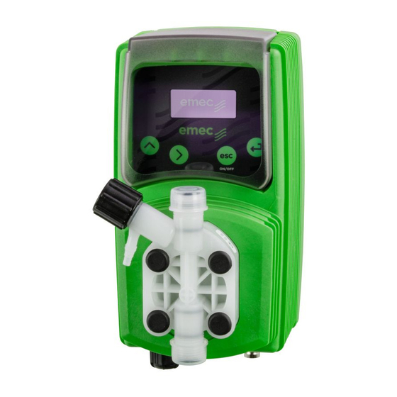
3. Pump’s description Display LCD Delivery valve Discharge knob Pump head Level probe input External Signal input Suction valve to power supply... -
Page 8: Before To Install Warnings
4. Before to Install warnings Pump’s installation and operativity is made in 4 main steps: Pump’s installation Hydraulic Installation (hoses, level probe, injection valve) Electrical Installation (main power connection, priming) Programming the pump. Before to start, please read carefully the following safety information. Protective clothes Wear always protective clothes as masks, gloves, safety glasses and further security devices during ALL installation procedure and while... -
Page 9: Installation Draw
5. Installation Draw Pump must be installed in a wall support at a maximum height (from tank’s bottom) of 1,5 meters. 1 - Dosing Pump 2 - Suction Hose 3 - Delivery Hose 4 - Injection Valve 5 - Air discharge 6 - Level Probe 7 - Foot Filter 8 - Power Cable... -
Page 10: Hydraulic Installation
6. Hydraulic Installation Hydraulic connections are: Suction Hose with level probe and foot filter Delivery Hose with injection valve Discharge Hose Suction Hose. Completely unscrew tightening nut from pump’s head and remove assembling components: tightening nut, holding ring and pipe holder. Assembly as shown in fig. - Page 11 Assembling foot filter with level probe. Level probe must be assembled with foot filter using the provided kit. Foot valve is made to be installed into tank’s bottom without sediments priming problem. STEP 5 STEP 4 INSERT RING AS SHOWN STEP 3 INSERT PROBE WITH N.O.
- Page 12 Discharge hose. Insert one side of discharge hose into discharge connector as shown in fig (C). Insert other side of discharge hose into product’s tank. During priming procedure product exceeding will flow into tank. To Delivery hose Discharge Knob Discharge hose To Suction hose fig (C) For priming procedure see page 14.
- Page 13 Self-venting pump head. to bleed hose to delivery hose to suction hose Self-venting pump head must be used when using chemicals that produce gas (i.e. hydrogen peroxide, ammonium, sodium hypoclorite at particular conditions). Hoses assembling procedure (including purge hose) is described in fig. (A). Notes: - suction, delivery and purge valves are DIFFERENT! Do not exchange them! - delivery and purge hoses are made of same material!
-
Page 14: Electrical Installation
7. Electrical Installation All electrical connections must be performed by AUTHORIZED AND QUALIFIED personnel only. Before to proceed, please, verify the following steps: - verify that pump’s label values are compatible with main power supply. - pump must be connected to a plant with a differential switch (0,03A sensitivity) if there isn’t a good ground. - Page 15 Once verified previous steps proceed as follows: - check that “BNC” of level probe has been connected as described in “Hydraulic Installation” chapter. - connect “BNC” and external signal to pump’s “INPUT” connectors. This input may be used as follows: - as pulse sender water meter or - as startup contact for “BATCH”...
-
Page 16: Basic Settings
Turn the pump on or off and exit from setup menu (without saving parameters) Enter / exit from setup menu (saving parameters) The “VMS MF” pump is equipped with a keyboard.To avoid any misunderstanding during next chapters all keys will be described as shown on this legend: ON/OFF “UP”... - Page 17 Saving / Discarding changes / Activating working mode Once edited data into setup menu it’s possible to save them by pressing “E” key or to discard them by pressing “ESC” key. To activate a working mode (Constant, Divide, Multiply, PPM, PERC, MLQ, Batch, Volt, mA) select the required mode and confirm it using “E”...
-
Page 18: Priming
To proceed follow these steps: connect all hoses to the pump; open discharge valve by completely turning the discharging knob (counter clock-wise). Power up the pump. After pump’s intro (fig.1): VMS MF R: 1.xx fig.1 the pump will show the “Delay” (pump’s activation delay) as shown fig.2:... -
Page 19: Pump's Functions Summary
10. Pump’s functions summary Pump’s functions summary During pump’s working mode is it possible to see furthers working information. Press more times the “UP” key to cycle through following information: STROKES 100 SPM constant MODE Working 150 SPM CONSTANT Mode SUPPLY Power Supply 220 VAC... -
Page 20: Pump's Functions Summary- Alarms
10. Pump’s functions summary- ALARMS If any alarm is active, in the menù “Pump’s functions summary” a general alarm display will show the symbol “#” and the number of alarm active at the moment. Enter into this menu with “RIGHT” key. The windows displayed show which alarms are active. -
Page 21: Quick Guide - Main Menu (Prog [1] Mode)
11. Quick Guide - Main Menu (Prog [1] Mode) PROG [1] Mode [1] MODE CONSTANT page 34 Mode [2] DIVIDE page 35 Mode [3] MULTIPLY PROG [2] page 36 page 19 SETUP Mode [4] page 37 Mode [5] PERC page 38 Mode [&] PROG [3] page 20... -
Page 22: Quick Guide - Main Menu (Prog [2] Setup)
12. Quick Guide - Main Menu (Prog [2] Setup) SET [01] CC/ST PROG [1] pag. 19 MODE pag. 22 Set [02] test pag. 22 set [03] level pag. 23 set [04] wmeter pag. 24 set [05] timeout PROG [2] SETUP pag. -
Page 23: Quick Guide - Main Menu (Prog [3] Stat)
13. Quick Guide - Main Menu (Prog [3] Stat) PROG [1] See pag. 19 MODE PROG [2] See pag. 20 SETUP PROG [3] ->TOt dos See pag. 38 counter STAT... -
Page 24: Setup
15. Setup Pump’s initial setup Apart of choosen working mode, the pump must be prepared to operate by setting the main parameters into “SETUP” menu. To enter into this menu please follow the “Quick Guide through menu” at page 20. CC per Stroke. - Page 25 Pre Level Alarm (Reserve). SET [03] This function defines a pre-alarm status to inform user that the dosing product is near to LEVEL end. Reserve value to be set, must be calculated on product quantity left between foot filter and pump’s suction level. - Use “UP”...
- Page 26 Water Meter Setup. Use this function to setup the water meter information. SET [04] wmeter By entering the amount of pulses produced by the water meter the pump will optimize the working mode when programmed to work in ppm and update the stats menu. Use “UP”...
- Page 27 Pulses Timeout (only for “Multiply” working mode and “PPM”, “PERC” and “MLQ” working mode when the result is a multiplication). SET [05] When the pump receives a pulse from the water meter it starts the dosing timeout activity through an amount of time (from the first pulse to the following one). At the beginning the pump doesn’t know the time lapse between the first and the second pulse.
- Page 28 Unit Change. SET [06] This function allows to choose between liters or gallons measurement unit. unit Use “UP” key to switch between liter or gallons measurement unit. Press “E” key to save data and “ESC” exit to main UNIT menu. Otherwise press “ESC” to discard data and exit to litre main menu.
- Page 29 Password Setup. “Setup” menu is password protected. Default value to enter into “setup” menu SET [12] is “0000” (only numeric units). To change this password proceed as follows: password Use “UP” key to change first digit. Press “RIGHT” key to move cursor over next digit. password Press “E”...
-
Page 30: Load Default" And "Reset Password" Procedure
16. “Load default” and “Reset Password” procedure “LOAD DEFAULT” procedure This procedure deletes all programming data set. It reloads the default data of the pump. Follow this instructions: - unplug power supply; - pressing both “UP” and “RIGHT” keys, plug in power supply. For few seconds, the display shows LOAD DEFAULT before start up the pump. -
Page 31: Working Procedure Setup
17. Working procedure setup Introduction. “MF” pump can work in differents modes. CONSTANT mode. Pump doses at a constant rate set in “SPH” (strokes for hour), “SPM” (strokes for minute) or “LPH” (litres per hour) parameters set during program session. When to use this mode ? This mode is useful when there isn’t an input signal to control the dosing activity. - Page 32 PERC mode. Dosing rate is determined by pulses from a water meter, percentage (%), chemical product concentration and quantity for each single stroke set during program session. When to use this mode ? This mode is useful using an external signal from a pulse sender water meter and it’s neces sary to specify only % , leaving the pump to manage coming pulses.
- Page 33 MLQ mode. Dosing rate is determined by pulses from a water meter on the base of set MLQ (milliliters per quintal), chemical product concentration (%) and quantity for each single stroke set during program session. When to use this mode ? This mode is useful when with an external signal from a pulse sender (as a water meter), it is necessary to dose the product quantity set specifing the MLQ (milliliters per quintal) and leaving the pump to manage the coming pulses.
-
Page 34: Constant" Working Mode
18. “CONSTANT” working mode CONSTANT mode. Pump doses at a constant rate set in“SPH” (strokes for hour), “SPM” (strokes for minute), “LPH” (litres per hour) parameters set during program session. Which parameters must be set ? SPH (strokes per hour), SPM (strokes per minute), LPH (litres per hour). mode [01] CONSTANT CONSTANT... -
Page 35: Divide" Working Mode
19. “DIVIDE” working mode DIVIDE mode. External pulses are divided by a value set during program session. The pump doses with a frequency determined by this parameter. Which parameters must be set ? DIVIDE (divisor factor) mode [02] divide DIVIDE 150.00 Use this mode if connected pulse sender water meter produces many pulses and pump must divide them for correct dosing activities. -
Page 36: Multiply" Working Mode
20. “MULTIPLY” working mode MULTIPLY mode. External pulses are multiplied by a value set during program session. The pump doses with a frequency determined by this parameter. Which parameters must be set ? MULTIPLY (multiply factor) TIMEOUT mode [03] multiply multiply 010.00 Use this mode if: connected pulse sender water meter produces few pulses and pump must... -
Page 37: Ppm" Working Mode
21. “PPM” working mode PPM mode. Dosing rate is determined by pulses from a water meter, PPM, chemical product (%) concentration and quantity for each single stroke set during program session. Which parameters must be set ? PPM (parts per million product quantity) CONC (% of product’s concentration) TIMEOUT WMETER (pulse sender water meter) -
Page 38: Perc" Working Mode
22. “PERC” working mode PERC mode. Dosing rate is determined by pulses from a water meter, percentage (%), chemical product concentration and quantity for each single stroke set during program session. Which parameters must be set ? % (percentage of product quantity to dose) CONC (% of product’s concentration): set 100% if product is pure CC/STROKE (refer to CC/ST setup) WMETER (water meter) -
Page 39: Mlq" Working Mode
23. “MLQ” working mode MLQ mode. Dosing rate is determined by pulses from a water meter on the base of set MLQ (milliliters per quintal), chemical product concentration (%) and quantity for each single stroke set during program session. Which parameters must be set ? MLQ (product quantity in milliliters per quintal) CONC (% of product’s concentration): set 100% if product is pure CC/STROKE (refer to CC/ST setup) -
Page 40: Batch" Working Mode
24. “BATCH” working mode BATCH mode. Signal from an external contact starts the pump to dose the needed quantity set during program session or for the set number of strokes. When to use this mode ? This function allows to begin dosing activities when pump receives an external signal or to dose in WORK-PAUSE mode. -
Page 41: Volt" Working Mode
25. “VOLT” working mode VOLT mode. Voltage from an external device drives the pump that doses proportionally using a minimum and maximum of strokes for minute set during program session. Which parameters must be set ? HIV (maximum tension) LOV (minimum tension) SPM (strokes per minute) mode [08] volt... -
Page 42: Ma" Working Mode
23. “mA” working mode mA mode. Current from an external device drives the pump that doses proportionally using a minimum and maximum of strokes for minute set during program session. Which parameters must be set ? HImA (maximum current) LOmA (minimum current) SPM (strokes per minute) mode [09] a 10.0... -
Page 43: Statistics Management
24. STATISTICS management Stat. To see dosing statistics choose “STAT” from main menu. See quick guide at pag. 21 prog [3] stat -> tot dos counter litres reset reset tot dos -> counter pulse reset reset “TOD DOS” means total dosed product since pump last reset. “COUNTER”... -
Page 44: Troubleshooting
25. Troubleshooting Problem Possible Cause Pump isn’t powered. Connect it to main supply. Pump’s protection fuse is broken. Replace it. See page replacement Pump doesn’t turn procedure. Pump’s main board is broken. Replace it. See page replacement procedure. The foot filter is obstructed. Clean it. Suction hose is empty. -
Page 45: Fuse And Main Board Replacement
26. Fuse and main board replacement Fuse or main board replacement is allowed to qualified personnel only. Before to operate disconnect the pump from main power and all hydraulic connections. For fuse replacement is necessary to use a 3x16 and 3x15 screwdriver and a new fuse (same model of old one). For main board replacement is necessary to use a 3x16 and 3x15 screwdriver and a new main board (same model of old one). -
Page 46: Main Board
FUSE MAIN POWER Coil Coil Power STBY supply Input Input Level Level On demand On demand level alarm level alarm repeater repeater VMS MF FOR WATER METER WITH HALL EFFECT CONNECTION Power supply FUSE Level Coil Input WHITE YELLOW BROWN... -
Page 47: A Appendix. Maintenance
A Appendix. Maintenance. In order to ensure the requirements of potable drinking water treated and the Maintenance schedule maintenance of the improvements as declared by the manufacturer, this equipment must be checked at least once a month. OPERATOR PROTECTION Use safety equipment according to the company regulations. Use this safety equipment within the work area during installation, service and when handling chemicals: •... - Page 48 f the pump performance does not satisfy your process requirements, and the process requirements have not changed, then perform these steps: 1. Disassemble the pump. 2. Inspect it. 3. Replace worn parts. This procedure SHOULD BE CARRIED OUT BY AUTHORIZED AND QUALIFIED Shutdown procedure PERSONNEL...
-
Page 49: B Appendix. Construction Materials And Technical Info
B Appendix. Construction Materials and Technical info TECHNICAL FEATURES Power supply: 230 VAC (190÷265 VAC) Power supply: 115 VAC (90÷135 VAC) Power supply: 24 VAC (20÷32 VAC) Power supply: 12 VDC (10÷16 VDC) Pump Strokes: 0 ÷ 180 Suction Height: 1,5 metres Environment Temperature: 0 ÷... -
Page 50: C Appendix. Delivery Curves
C Appendix. Delivery Curves Pump Head J Pump Head K 20 01 18 04 l/h 01 l/h 04 bar 20 bar 18 Pump Head K Pump Head K 18 02 15 04 l/h 02 l/h 04 bar 18 bar 15 Pump Head K Pump Head K 10 10... - Page 51 Pump head K Pump head K 07 06 05 10 l/h 06 l/h 10 bar 07 bar 05 Pump head K Pump head K 05 01 05 12 l/h 01 l/h 12 bar 05 bar 05 Pump head K Pump head K 04 08 03 10 l/h 08...
-
Page 52: C Appendix. Self-Venting Delivery Curves
C Appendix. Self-Venting Delivery Curves Pump Head KA Pump Head KA 15 03 18 02 3 bar 2 bar 15 l/h 18 l/h Pump Head KA Pump Head KA 15 01 10 3.4 1 bar 3.4 bar 15 l/h 10 l/h Pump Head KA Pump Head KA 10 02... - Page 53 Pump head KA 03 07 7 bar 3 l/h Flow rate indicated is for H O at 20°C at the rated pressure. Dosing accuracy ± 2% at constant pressure ± 0,5 bar.
-
Page 54: D Appendix. Dimensions
D Appendix. Dimensions DIMENSIONS inch 106.96 4.21 210.44 8.28 199.44 7.85 114.50 4.50 187.96 7.40 97.00 3.81 106.96 4.21 125.47 4.93 50.00 1.96 201.00 7.91... -
Page 55: E Appendix. Chemical Compatibility Table
EMEC makes warranties of any matter respect to the informations provided in this list. -
Page 56: F Appendix. Hoses Resistance Table
F Appendix. Hoses resistance table Hose features are very important for a reliable dosage. Every pump’s model is made to work in the best way using selected hoses according to pump’s capacity / model. Information reported here are intended for standard use only. For extended information ask to hose’s manufacturer. - Page 58 MOD 7.5 B1 Q Ed. 1 - rev. 0 21/02/2012 PRODUCT SERVICE REPAIR FORM ENCLOSE THE PRESENT FORM TO THE DELIVERY NOTE DATE ..........SENDER Company name ............................Address ..............................Phone no..............................Contact person............................. PRODUCT TYPE (see product label) DEVICE CODE ..............................
-
Page 59: Table Of Contents
Summary GENERAL SAFETY GUIDELINES ....................2 PURPOSE OF USE AND SAFETY ....................3 ENVIRONMENTAL SAFETY ......................4 LABELS ............................4 SPARE PARTS ..........................4 1. Introduction ..........................5 2. Unpacking ..........................6 3. Pump’s description ........................7 4. Before to Install warnings ......................8 5. Installation Draw ........................9 6. Hydraulic Installation .......................10 7. - Page 60 When dismantling a pump please separate material types and send them according to local recycling disposal requirements. We appreciate your efforts in supporting your local Recycle Environmental Program. Working together we’ll form an active union to assure the world’s invaluable resources are conserved.
Need help?
Do you have a question about the VMS MF and is the answer not in the manual?
Questions and answers