
Subscribe to Our Youtube Channel
Summary of Contents for Clarke CDM45C
- Page 1 DIGITAL MULTIMETER MODEL NO: CDM45C PART NO: 4501155 OPERATING INSTRUCTIONS GC0415...
-
Page 2: Environmental Recycling Policy
INTRODUCTION Thank you for purchasing this CLARKE product. Before attempting to use this product, please read this manual thoroughly and follow the instructions carefully. In doing so you will ensure the safety of yourself and that of others around you, and you can look forward to your purchase giving you long and satisfactory service. -
Page 3: Safety Information
SAFETY INFORMATION WARNING: TAKE CARE WHEN USING THIS METER. IMPROPER USE CAN RESULT IN ELECTRIC SHOCK OR DAMAGE TO THE METER. TAKE ALL NORMAL SAFETY PRECAUTIONS AND FOLLOW THE SAFEGUARDS SUGGESTED IN THIS MANUAL. BEFORE USE 1. When using the meter, the user must observe all normal safety rules concerning: •... -
Page 4: Specifications
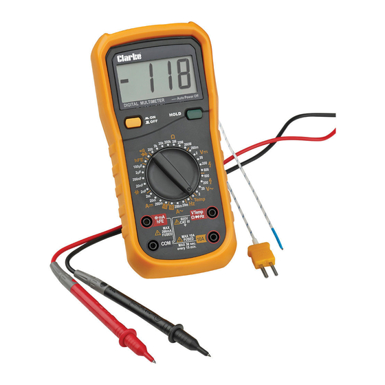
12. Do not store or use the meter in areas exposed to direct sunlight, at high temperature or with high relative humidity. 13. To avoid false readings, replace the batteries as soon as the Low Battery indicator appears. 14. Before use, verify the meter operation by measuring a known voltage. 15. - Page 5 FEATURES OF THE METER Feature Description/Use Display Digital LCD Power Button Power ON/OFF Data Hold Press the HOLD button. The LCD will hold the last Button reading measured and display the ‘H’ symbol. When the button is released, the meter will return to normal. Rotary Switch Selects different functions and range.
-
Page 6: Items Supplied
MEASUREMENT FEATURES OF THIS METER • Alternating voltage measurement:- V~ • Direct voltage measurement:- V= • Alternating current measurement:- A= • Direct current measurement:- A= Ω • Resistance measurement:- • Diode measurement:- • Continuity:- • Capacitance:- • Frequency measurement:-Hz • Temperature:- Temp •... -
Page 7: Operation
OPERATION Before taking the measurement of voltage with the probe, make sure there is no electronic device connected to the test socket of the instrument. PREPARATION 1. Switch on the power by turning the rotary switch. If the battery voltage is lower than 7V, the symbol will appear and the battery should be replaced. -
Page 8: Dc/Ac Current Measurement
When “l “is shown on the LCD, it means the measurement has exceeded the allowable range and a higher range should be selected. When the scale of the value to be measured is unknown, select the highest range first and lower the range accordingly. DC/AC CURRENT MEASUREMENT WARNING: USE CAUTION WHEN MEASURING HIGH VOLTAGE CIRCUITS TO AVOID ELECTRICAL SHOCK AND INJURY. - Page 9 4. Read the value on the LCD. NOTE: When the input is open, "1 " is displayed on the LCD to indicate Ω overload. For measuring resistance above 1M , it may take a few seconds to get a steady reading. This is normal for high resistance measurement.
-
Page 10: Frequency Measurement
3. Connect the test leads to two ends of the circuit/ capacitor and read the value on the LCD. FREQUENCY MEASUREMENT 1. Plug the black test lead into the "COM" jack and the red test lead into the Ω “VTemp Hz"... -
Page 11: Technical Specifications
TECHNICAL SPECIFICATIONS DC VOLTAGE Range Resolution Accuracy µ 200mV ± 0.5% of reading, + 2 digits 10mV 200V 100mV 600V ± 0.8% of reading, + 2 digits • Max input voltage: 250V DC at 200mV range, 600V DC elsewhere. • Input impedance: 10MΩ NOTE: At low voltage ranges, unsteady readings will appear before the test leads make contact with the circuit. - Page 12 DIRECT CURRENT Range Resolution Accuracy 1µA ± 0.8% of reading, +1 digits 20mA 10µA 200mA 100µA ± 1.5% of reading, +1 digits 10mA ± 2% of reading, + 5 digits • Overload protection: F1 400mA/600V Fuse F2 10A/600V • 10A range: F2, 10A/600V fuse (quick acting). •...
- Page 13 TEMPERATURE Range Resolution Accuracy -20C°- 0C° 1C° ± 5% of reading, + 4 digits 1C°- 400C° 1C° ± 2% of reading, + 3 digits 40C°- 1000C° 1C° ± 2% of reading, + 5 digits RESISTANCE Range Resolution Accuracy 200Ω 0.1Ω ±...
-
Page 14: Maintenance
4. Clip the battery compartment to the casing and tighten the screw. REPLACING FUSES Fuses rarely need replacement. Almost all fuse blows are the result of operator error. Fuses should be replaced by the Clarke Service Department with the type(s) stated on page 4. TEST LEAD REPLACEMENT WARNING: REPLACE THE TEST LEADS WITH IDENTICAL OR COMPATIBLE LEADS. -
Page 15: Declaration Of Conformity
DECLARATION OF CONFORMITY Parts & Service: 020 8988 7400 / E-mail: Parts@clarkeinternational.com or Service@clarkeinternational.com...
Need help?
Do you have a question about the CDM45C and is the answer not in the manual?
Questions and answers