Advertisement
Quick Links
Advertisement

Summary of Contents for FitLux 5200
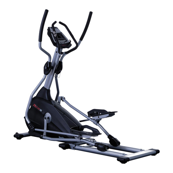
- Page 1 FitLux 5200 ELLIPTICAL TRAINER Owner's Manual Made in Taiwan...
-
Page 2: Table Of Contents
INDEX IMPORTANT NOTICE . . . . . . . . . . . . . . . . . . . . . P . 1 ASSEMBLY PARTS LIST . -
Page 3: Important Notice
IMPORTANT NOTICE: THIS EQUIPMENT IS ONLY FOR HOME USE, NOT FOR COMMERCIAL PURPOSE. USER'S WEIGHT SHOULD BE LIMITED ONLY TO 150 KGS. 1 . Before proceeding into any type of exercise program, it is recommended that one should first consult a physician . 2 . -
Page 4: Assembly Parts List
Assembly No. Llist ASSEMBLY PARTS LIST A . SCREW . . . . . . . . . . . . . . . 4 1 . MAIN FRAME . . . . . . . . . . . . 1 B . -
Page 5: Assembly Instruction
Assembly Instruction Step 1. Step 2. Attach Bottom Frame (2) to Main Frame 1 . Remove the bolts at the front top of (1), secure by Screw(A), Bolt & Nut (B) . Main Frame . Please keep the Computer Wire outside of tube for further assembly . - Page 6 Assembly Instruction Step 5. 1 . For the convenience of users, Shaft (D) has been inserted to connect Pedal Support (3) and Pull Rod (6) and secure by Screw & Washer (D) . All you need is to choose the set with sticker shown L to place on the left side of Main Frame (1) and place the wheel on one end of Pull...
- Page 7 Step 7. Step 6. Place Computer (8) at the top of Handlebar Well connect wire and cable from Post (5) then push all cable and wire inside Handlebar Post (5) and Computer (8) . handlebar post and secure by the screws provided by the computer .
- Page 8 Assembly Instruction Step 10. Step11. Attach Joint Cover (11) to the bottom Attach Top Joint Cover (7) to the Swing joint of Swing Handlebar (4), secure by Handlebar (4), secure by Screw (7) Screw (11) . Firstly do the assembly on the left side of Main Frame .
-
Page 9: Computer Instruction
Computer Instruction The monitor is designed for programmable magnetic bikes and introduced with the following categories: • Key Functions • About Displays • Operating Ranges • Things You Should Know Before Exercising • Operation Instructions • Key Functions There are total 6 keys including START/STOP, ENTER, MODE, UP, DOWN, and RECOVERY . - Page 10 Computer Instruction C . PROGRAM No .: Indicates the programs selected from PROGRAM 1 to PROGRAM 16 D . LEVEL No .: Indicates the level of loading selected from LEVEL 1 to LEVEL 16 . E . GENDER: Indicates the gender (Male or Female) selected . F .
- Page 11 Computer Instruction K. HEART RATE/BODY TYPE Display: Indicates only one value of HEART RATE or BODY TYPE displayed depending on the programs . L . LOADING Profiles: There are 10 columns of loading bars, and 8 bars in each column . Each column represents 3 minutes workout (without the change of TIME value), and each bar represents 2 levels of loading .
- Page 12 Computer Instruction • Things You Should Know Before Exercising A . The values calculated or measured by the computer are for exercise purpose only, not for medical purpose . B . The Variables May Need To Change In The Programs: Programs Variables P1 ~ P7...
- Page 13 Computer Instruction Program 5 (Ramp) Program 6 (Mountain) Program 7 (Random) Program 8 (Body Fat) Program 9 (Target H .R .) Program 10 (60% H .R .C .) Program 11 (75% H .R .C .) Program 12 (85% H .R .C .) Program 13 (User Setting) Program 14 (User Setting) Program 15 (User Setting)
- Page 14 Computer Instruction E . Body Types: There are 9 body types divided according to the FAT% calculated . Type 1 is from 5% to 9% . Type 2 is from 10% to 14% . Type 3 is from 15% to 19% . Type 4 is from 20% to 24% .
- Page 15 Computer Instruction Preset Programs: PROGRAM 2 to PROGRAM 7 are the preset programs . Press “ENTER” key to select TIME, DISTANCE, CAL and AGE . Then, press▲ or ▼ key to adjust the values . Users may exercise with different level of loading in different intervals as the profiles show .
- Page 16 Computer Instruction User Setting Programs: Program 13 to Program 16 are the user-setting programs . Users are free to edit the values in the order of TIME, DISTANCE, AGE, CAL and the level of loading in 10 intervals . The values and profiles will be stored in the memory after setup . After pressing “START/STOP”...
- Page 17 Computer Instruction LCD/LED W/ PROGRAM MONITOR TROUBLE SHOOTING GUIDE Symptom Possible Cause Solution You have the wrong Check that the Batteries or the Adaptor Specifications Adaptor or the wrong coincide with Intruction Manual Specifications . Batteries? The Mains Power switch is Check that the Mains Power is switched on and is The LCD turmed off?
- Page 18 Computer Instruction Symptom Possible Cause Solution The Computer is NOT Check that the Ear Clip Plug is FIRMLY inserted into the receiving a Pulse Computer . Signal . 1) The Ear Clip Pulse Sensors will NOT operate correctly if yours truly skin is extremely dry, dab a little water onto No Ear The Computer is your earlobe and try again .
- Page 19 Computer Instruction LCD W/PROGRAM MONITOR TROUBLE SHOOTING GUIDE Symptom Possible Cause Solution 1) Review the Assembly Instructions and check that all the Computer Plugs and Sockets are FIRMLY and correctly connected . 2) Review the Bike's Magnetic Resistance System to ensure that it is set correctly and the be at it can freely be adjusted .
-
Page 20: Exploded Drawing
Exploded Drawing... -
Page 21: Parts List
Parts List NO. DESCRIPTION Q'ty. NO. DESCRIPTION Q'ty. Main Frame Bottom Frame Spacer Ø15xØ17x4T End Cap Bearing #6002 Foot Pad Bracket Aluminum Rail Bolt M10x55mm Screw M10x16mm Bolt M10x80mm Screw M8x16mm Nut M10 Computer Screw M4x12mm Screw Pull Rod Audio Cable Screw M8x16mm Hand Pulse Plate (A) Washer Ø8x Ø25x 1 .5T... - Page 24 Factory: JIH KAO ENTERPRISE CO., LTD...
Need help?
Do you have a question about the 5200 and is the answer not in the manual?
Questions and answers