Table of Contents
Advertisement
Quick Links
Advertisement
Table of Contents

Summary of Contents for Speco O4B2M
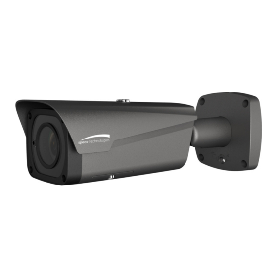
- Page 1 Quick Start Guide 4MP Bullet IP Camera O4B2M...
- Page 2 This owner’s manual is designed to be a reference tool for your system. Please read this manual carefully before operating the unit and retain it for future reference. Should you require any technical assistance, please contact Speco Technologies Technical Support.
- Page 3 Important Safeguards and Warnings . . . . E lectrical safety All installation and operation here should conform to local electrical safety codes. Use a certified/listed 12VDC Class 2 power supply only. Please note: Do not connect two power supplying sources to the device at the same time; it may result in device damage! The product must be grounded to reduce the risk of electric shock.
- Page 4 Speco Technologies is not liable for any loss caused by improper operation. Note: Before installation, check the package and make sure that all components are included. Contact your rep or Speco customer service department immediately if something is broken or missing in the package. Accessory Name...
-
Page 5: Table Of Contents
Table of Contents Structure ..........................1 External Cable ......................1 Dimensions ......................... 2 Alarm Setup ........................ 2 Device Installation ........................4 IP Scanner ..........................6 Operation ........................6 Web Operation......................... 7 Login and Main Interface .................... 7... -
Page 6: Structure
1 Structure 1.1 External Cable Note: You can refer to the following figure for cable information. See Figure 1-1 Figure 1-1 Please refer to the following sheet for detailed information. No. Port Name Function Connector Note AUDIO OUT Audio output port RCA Output audio signal to speaker AUDIO IN Audio input port... -
Page 7: Dimensions
1.2 Dimensions Note: Please refer to the following figure for dimension information. The unit is mm. See Please refer to the following figure for dimension information. The unit is mm. See Figure 1 1- 2. Figure 1-2 1.3 Alarm Setup Figure1-3 Alarm input, output description: Step 1... - Page 8 Please refer to the following figure for alarm input information. See Figure 1-4. Alarm input: When the input signal is idle or grounded, the device can collect the different status of the alarm input port. When the input signal is connected to 3.3V or it is idle, the device collects logic “1”. When the input signal is grounded, the device collects logic “0”.
-
Page 9: Device Installation
2 Device Installation Note: Before installation, please make sure the installation surface can support a minimum of 3 times the weight of the camera Figure 2-1 Please see Figure 2-1. Step 1 Stick installation position template to designated surface where you will install the device (wall or ceiling). Step 2 Drill holes according to the position of the holes marked on the installation template. - Page 10 Figure 2-2 Please be sure to loosen the adjusting screw when adjusting the device position and angle, tighten the adjusting screw after adjustment. Continuous rotation towards the same direction for the camera body has to be within 3 circles. Step 6 Use screwdriver (in accessories bag) to loosen adjusting screw.
-
Page 11: Ip Scanner
3 IP Scanner IP Scanner can search for the device on the local network. IP Scanner can search for the device on the local network. Please note that only devices that are on the same subnet can be discovered. Please note that only devices that are on the same subnet can be discovered. The device is set to DHCP mode by default. -
Page 12: Web Operation
4 Web Operation This device supports viewing and management via a web browser on a PC. This device supports viewing and management via a web browser on a PC. 4.1 Login and Main Interface Login and Main Interface Open the browser and input network camera address in the address bar or double click the device in IP Open the browser and input network camera address in the address bar or double click the device in IP Open the browser and input network camera address in the address bar or double click the device in IP Scanner.
Need help?
Do you have a question about the O4B2M and is the answer not in the manual?
Questions and answers