Table of Contents
Advertisement
Quick Links
Advertisement
Table of Contents

Summary of Contents for Chauvin Arnoux C.A 6113
- Page 1 C.A 6113 INSTALLATION TESTER User's manual E N G L I S H...
- Page 2 Thank you for purchasing a C.A 6113 installation tester. To obtain the best service from your unit: „ read these operating instructions carefully, „ comply with the precautions for use. WARNING, risk of DANGER! The operator must refer to these instructions whenever this danger symbol appears.
-
Page 3: Table Of Contents
CONTENTS 1. FIRST START-UP ..................................4 1.1. Unpacking ..................................4 1.2. Charging the battery ............................... 5 1.3. Carrying the device ................................ 5 1.4. Contrast and brightness of the display .......................... 6 1.5. Use on a desktop ................................6 1.6. Choice of language ................................ 7 2. -
Page 4: First Start-Up
• ” One C.A 6113. One mains charger with cable for the battery. One tripod cable with mains plug (adapted to the country of sale. One measuring cable, 3 safety leads. Three probe tips (red, blue, and green). -
Page 5: Charging The Battery
1.2. CHARGING THE BATTERY Before the first use, start by fully charging the battery. The charging must be done between 10 and 35°C. > 90 Vac < 264 Vac 50 / 60 Hz Battery loading... The indicator of the device lights. Battery charging connector of the device. -
Page 6: Contrast And Brightness Of The Display
To withdraw the strap, slide a flat screwdriver under the tab of the fastener to lift it, then slide the fastener down. 1.4. CONTRAST AND BRIGHTNESS OF THE DISPLAY To adjust the contrast and the brightness of the display, press the key and one of the arrow keys simultaneously. -
Page 7: Choice Of Language
1.6. CHOICE OF LANGUAGE Before using the device, first choose the language in which you want the device to display messages. Set the switch to SET-UP. Use the directional keypad to select the languages icon: SET UP Press the OK key to validate your choice. -
Page 8: Presentation Of The Device
2. PRESENTATION OF THE DEVICE TEST button to start Switch for selection the measurements. of the measurement function or SETUP. Connection terminals. TEST SET UP Four function keys. Indicator light. Directional keypad: four navigation keys and one validation key. Backlight lighting and adjust- Stud for fixing on ment key (contrast and bright-... -
Page 9: Functions Of The Device
2.1. FUNCTIONS OF THE DEVICE The C.A 6113 installation tester is a portable measuring device with a monochrome graphic display. It is powered by a recharge- able battery with a built-in charger and external power supply unit. This device is intended to check the safety of electrical installations. It can be used to test a new installation before it is powered up, to check an existing installation, whether in operation or not, or to diagnose a malfunction in an installation. -
Page 10: Display Unit
2.3. DISPLAY UNIT ➁ ➃ ➄ ➂ 50 . 0 Ω 50 . 1 Hz ➀ 02/09/2014 10:47 ➆ 6 mA 230.3 V L-PE 230.4 V ➅ ➇ 0.8 V N-PE ➈ LOOP Z ➉ Top strip Position of the phase on the socket outlet Date and time Display of measurement results Alarm threshold... -
Page 11: Procedure
3. PROCEDURE 3.1. GENERAL When it leaves the plant, the device is configured so that it can be used without changing the parameters. For most meas- urements, simply select the measurement function by turning the switch and press the TEST button. However, you can also parameterize: „... - Page 12 3.2.2. MAKING A MEASUREMENT Connect the leads to the device to be tested. As soon as the device is powered up, it measures the voltages present on its ter- minals and displays them, whatever the setting of the switch. The mains socket outlet of the measuring cable is marked with a white reference spot. : the phase is on the right-hand contact of the mains plug when the white spot is up.
-
Page 13: Resistance And Continuity Measurement
3.3. RESISTANCE AND CONTINUITY MEASUREMENT 3.3.1. DESCRIPTION OF THE MEASUREMENT PRINCIPLE For continuity measurements, the device generates a DC current of 200 or 12 mA, at the user’s discretion, between the W and COM terminals. It then measures the voltage present between these two terminals and from it deduces the value of R = V/I. For resistance measurements (current chosen = kW), the device generates a DC voltage between the W and COM terminals. - Page 14 Automatic reversal of polarity for a measurement at 200 mA. Measurement at positive polarity only. Measurement at negative polarity only. To activate the alarm. To deactivate the alarm. Ω 002.00 To set the alarm threshold (see §3.14). The default threshold is 2W. k Ω...
- Page 15 To see the next display page. 2.00 Ω - - .- Hz 02/10/2014 10:47 0 . 0 V External voltage present on the Ω terminals just before the start of the measurement. Use the key to return to the previ- ../..
- Page 16 „ In the case of a resistance measurement (kW), there is no current reversal and no compensation for the measurement leads. 2.00 kΩ - - .- Hz 02/10/2014 10:47 Value of the alarm threshold. 1 . 5 8 k Ω Measurement result.
-
Page 17: Insulation Resistance Measurement
3.4. INSULATION RESISTANCE MEASUREMENT 3.4.1. DESCRIPTION OF THE MEASUREMENT PRINCIPLE The device generates a DC test voltage between the COM and MW terminals. The value of this voltage depends on the resistance to be measured: it is greater than or equal to U when R is greater than or equal to R /1 mA, and less otherwise. - Page 18 3.4.3. CONFIGURING THE MEASUREMENT Before starting the measurement, you can configure it by modifying the parameters displayed: To choose the nominal test voltage UN: 50, 100, 250, 500 or 1000 V. To activate the alarm. To deactivate the alarm. k Ω 0500.0 To set the alarm threshold (see §3.14).
- Page 19 To see the next display page. 500 kΩ - - .- Hz 02/11/2014 10:47 External voltage present on the 0 . 0 V M Ω terminals just before the start of the measurement. Press TEST until the measurement Use the key to return to the previ- is stable ../..
-
Page 20: Earth Resistance Measurement
3.5. 3P EARTH RESISTANCE MEASUREMENT This function is the only one that can measure an earth resistance when the electrical installation to be tested is not live (new installation, for example). It uses two additional rods, with the third rod being constituted by the earth electrode to be tested (whence the name “3P”). - Page 21 To activate the alarm. To deactivate the alarm. Ω 050.00 To set the alarm threshold (see §3.14). As default, the threshold is set to 50W. k Ω If the measurement must be made in a damp environment, remember to change the value of maximum contact voltage in Setup (see §5) and set it to 25 V.
- Page 22 3.5.5. VALIDATION OF THE MEASUREMENT To validate your measurement, move the S rod towards the H rod by 10% of d and make another measurement. Then move the S rod, again by 10% of d, but towards the earth electrode. 52% d 62% d 72% d...
- Page 23 3.5.7. ERROR INDICATION The commonest errors in the case of an earth measurement are the presence of an interference voltage or rod resistances that are too high. If the device detects: „ a rod resistance greater than 15 kW, „ a voltage greater than 25 V on H or on S when the TEST button is pressed. In these two cases, the earth measurement is not enabled.
-
Page 24: Loop Impedance Measurement (Z )
3.6. LOOP IMPEDANCE MEASUREMENT (Z In a TN or TT type installation, the loop impedance measurement is used to calculate the short-circuit current and to size the protections of the installation (fuses or RCDs), especially their breaking capacity. In a TT type installation, the loop impedance measurement makes it easy to determine the earth resistance without planting any rods and without cutting off power to the installation. - Page 25 For a more accurate measurement, you can choose a high current (TRIP mode), but the RCD that protects the installation may trip. The alarm, if activated, serves to inform the user, by an audible signal, that the measurement is above threshold, making it un- necessary to look at the display unit to check this point.
- Page 26 3.6.4. READING OF THE RESULT „ In the case of a non-tripping measurement, with smoothing: Value of the alarm threshold. 50 .0 Ω 50 . 1 Hz 02/16/2014 10:47 Value of the short-circuit current. 6 mA Value of the impedance. Value of the resistance.
-
Page 27: Measurement Of The Line Impedance (Z )
3.7. MEASUREMENT OF THE LINE IMPEDANCE (Z The loop impedance measurement Zi (L-N, L1-L2, or L2-L3 or L1-L3) is used to calculate the short-circuit current and size the protec- tions of the installation (fuse or RCD), whatever type of neutral the installation uses. 3.7.1. - Page 28 3.7.3. CONFIGURING THE MEASUREMENT Before starting the measurement, you can configure it by modifying the parameters displayed: To activate or deactivate the smoothing of the signal. To compensate for the resistance of the measurement leads, for measurements of low values (see §3.13). The device proposes choosing the voltage for the Ik calculation from among the following values: „...
- Page 29 3.7.4. 3.6.3. READING OF THE RESULT Value of the alarm threshold. 50 . 0 Ω 50 . 1 Hz 02/18/2014 10:47 Value of the short-circuit current. Value of the impedance. Value of the resistance. 1 3 1 6 A Value of the inductance. Case where the measurement is 0 .
- Page 30 3.8. EARTH MEASUREMENT ON LIVE CIRCUIT (Z This function is used to make an earth resistance measurement in a place where it is impossible to make a 3P earth measurement or to disconnect the earth connection strap, often the case in an urban environment. This measurement is made without disconnecting the earth, with only one additional rod, saving time with respect to a conven- tional earth measurement with two auxiliary rods.
- Page 31 To make this measurement, you can choose: „ either a low current which avoids any untimely tripping out of the installation but gives only the earth resistance (RA). „ or a high current (TRIP mode), which yields a more accurate earth impedance (ZA) with good measurement stability. The alarm, if activated, serves to inform the user, by an audible signal, that the measurement is above threshold, making it un- necessary to look at the display unit to check this point.
- Page 32 3.8.4. READING OF THE RESULT „ In the case of a measurement with a high current (TRIP mode), without smoothing: Value of the alarm threshold. 50 . 0 Ω 50 . 1 Hz 02/20/2014 10:47 Value of the short-circuit current. Earth electrode fault voltage in the event of a short-circuit.
- Page 33 To see the next display page. 50 . 0 Ω 50 . 1 Hz 02/20/2009 10:47 2 5.1 0 Ω Value of the impedance. 2 4 . 8 Ω Value of the resistance. 5 . 6 Value of the inductance. Use the ...
- Page 34 3.8.5. VALIDATION OF THE MEASUREMENT Move the rod ± 10% of the distance from the earth electrode and make two more measurements. The 3 measurement results must be the same to within a few percent. In this case the measurement is valid. If this is not the case, this means that the rod is in the zone of influence of the earth electrode.
-
Page 35: Selective Earth Measurement On Live Circuit
3.9. SELECTIVE EARTH MEASUREMENT ON LIVE CIRCUIT This function is used to make an earth measurement and to select one earth from among others, in parallel, and measure it. It requires the use of an optional current clamp. The C177 and MN77 clamps are better suited to these measurements because they are ten times as sensitive as the C177A clamp. - Page 36 In the selective earth measurement on live circuit, it is essential to do a compensation of the measurement leads and to redo it if it has not been done recently or if you have changed leads. 3.9.3. CONFIGURING THE MEASUREMENT Before starting the measurement, you can configure it by modifying the parameters displayed: The measurement current must be a high current (TRIP mode).
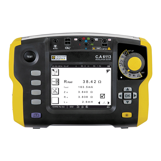
- Page 37 3.9.4. READING OF THE RESULT Value of the alarm threshold. Ω 50 . 1 Hz 02/23/2014 10:47 Measurement result. Value of the current measured by the clamp. Value of the impedance. 3 8.4 2 Ω Asel Value of the resistance. Value of the inductance.
-
Page 38: Test Of Residual Current Device
3.10. TEST OF RESIDUAL CURRENT DEVICE The device can be used to perform three types of test on RCDs: „ a tripping test in ramp mode, „ a tripping test in pulse mode, „ a non-tripping test. The test in ramp mode serves to determine the exact value of the tripping current of the RCD. The test in pulse mode serves to determine the tripping time of the RCD. - Page 39 If possible, first disconnect all loads from the network on which you test the RCD. This prevents interference with the test by any leakage currents due to these loads. If you have a current clamp, you can measure the leakage current (see §3.11) at the RCD and so make allowance for it during the test.
- Page 40 3.10.3. CONFIGURING THE MEASUREMENT Before starting the measurement, you can configure it by modifying the parameters displayed: „ Choice of the nominal current of the residual current device I : VAR. (variable: the user programs a value be- tween 6 and 999 mA), 10 mA, 30 mA, 100 mA, 300 mA, 500 mA, 650 mA, or 1000 mA. 30 mA „...
- Page 41 3.10.4. READING OF THE RESULT 50 . 1 Hz 02/24/2014 10:47 30 mA or R 1.0 7 3 V Tripping current. 2 2.3 m A Tripping time. 1 3.8 m s The measurement results are correct. The key is used to see the voltages .
- Page 42 3.10.5. MAKING A TEST IN PULSE MODE Connect the measuring cable to the device, then to a socket outlet included in the circuit protected by the circuit-breaker to be tested. Set the switch to RCD At the time of connection, the device detects the positions of the phase (L) and SET UP of neutral (N) with respect to the protective conductor (PE) and displays them.
- Page 43 3.10.6. CONFIGURING THE MEASUREMENT Before starting the measurement, you can configure it by modifying the parameters displayed: Choice of the nominal current of the residual current device I : VAR. (variable: the user programs a value between 6 and 999 mA), 10 mA, 30 mA, 100 mA, 300 mA, 500 mA, 650 mA or 1,000 mA. 30 mA „...
- Page 44 Type of RCD max (ms) Standard I Test Press the TEST button to start the measurement. The measurement stops automatically. In the case of type S or G RCD, the device counts 30 seconds between the prior test of UF and the test of the RCD itself, in order to allow its demagnetization.
- Page 45 „ In the case of a non-tripping test in pulse mode: 50 . 1 Hz 02/25/2014 10:47 30 mA or R 0.1 4 6 V The RCD did not trip out during the duration of application of the current of 0.5 I >...
-
Page 46: Current And Leakage Current Measurement
3.11. CURRENT AND LEAKAGE CURRENT MEASUREMENT This measurement requires the use of a specific optional current clamp. It can measure very low currents (of the order of a few mA) like fault currents or leakage currents, and high currents (of the order of a few hundred Amperes). - Page 47 3.11.4. READING OF THE RESULT 010 . 0 A 50 . 1 Hz 02/26/2014 10:47 Value of the alarm threshold. 1 9 7.3 m A Measurement result. Case where the measurement is below the alarm threshold. CURRENT The clamp is connected. 3.11.5.
-
Page 48: Direction Of Phase Rotation
3.12. DIRECTION OF PHASE ROTATION This measurement is made on a three-phase network. It is used to check the phase order of the network. 3.12.1. DESCRIPTION OF THE MEASUREMENT PRINCIPLE The device checks that the three signals are at the same frequency, then compares the phases to determine their order (direct or reverse direction). - Page 49 3.12.4. ERROR INDICATION The commonest errors in the case of a test of direction of phase rotation are: „ One of the three voltages is outside the measurement range (connection error). „ The frequency is outside the measurement range. For help with connections or any other information, use the help function.
-
Page 50: Compensation For The Resistance Of The Measurement Leads
3.13. COMPENSATION FOR THE RESISTANCE OF THE MEASUREMENT LEADS Compensation for the resistance of the measurement leads serves to neutralize their values and obtain a more accurate meas- urement when the resistance to be measured is low. The cords are already compensated in the plant, but if you use cords other than those provided, you can perform a new compensation. - Page 51 3.13.4. ELIMINATING THE COMPENSATION Proceed as for compensation, but rather than short-circuiting the leads, leave them disconnected. Then press the TEST button. R∆ The device removes the compensation, then returns to voltage measurement. The symbol disappears from the display unit and the icon is crossed out.
-
Page 52: Adjustment Of The Alarm Threshold
3.14. ADJUSTMENT OF THE ALARM THRESHOLD The device makes an audible signal and the indicator flashes: „ in continuity, resistance and insulation measurement, if the measurement is below threshold; „ for earth and loop measurement, if the measurement is above threshold; „... -
Page 53: Error Indication
4. ERROR INDICATION Generally, errors are reported in clear language on screen. Example of error screen: Press the OK key to erase the message. Or press the help key for help in solving your problem. The following screen is then displayed. ... -
Page 54: No Connection
4.1. NO CONNECTION One or more terminals are not connected. 4.2. OUT OF MEASUREMENT RANGE > 4 0 . 0 W The value is outside the measurement range of the device. The minimum and maximum values depend on the function. <... -
Page 55: Check Of Internal Protection Devices
4.6. CHECK OF INTERNAL PROTECTION DEVICES The device includes two internal protection devices that cannot be reset and that the user cannot replace. These devices act only under extreme conditions (e.g. a lightning strike). To check the condition of these protections: Disconnect the input terminals. -
Page 56: Set-Up
5. SET-UP Set the switch to SET-UP. SET UP SET-UP Use the directional keypad to select an icon, select a field, and modify it. This key is used to exit from the current screen without saving. Used to display all parameters of the device: „... - Page 57 Adjustment of the time to automatic switching off of the backlighting: 1 min, 2 min (default), 5 min, or 10 min. ∞ Adjustment of the time to automatic switching off of the device: 5 min (default), 10 min, 30 min, or (per- manent operation).
- Page 58 Direction of phase rotation „ No configuration. To choose the language.
-
Page 59: Technical Characteristics
6. TECHNICAL CHARACTERISTICS 6.1. GENERAL REFERENCE CONDITIONS Quantity of influence Reference values Temperature 20 ± 3 °C Relative humidity 45 to 55 % HR Supply voltage 9.6 ± 0.2 V Frequency DC and 45 to 65 Hz Electric field < 1 V/m Magnetic field <... - Page 60 Measurements of potential of the voltage probe The characteristics are the same as in the voltage measurements. This voltage must normally be between 0 and U 6.2.2. FREQUENCY MEASUREMENTS Particular reference conditions: Voltage ≥ 2 V ≥ 30 mA for the MN77 clamp, or current ≥...
- Page 61 6.2.4. RESISTANCE MEASUREMENTS Particular reference conditions: External voltage on the terminals: zero. Measurement range 0.0 - 3.999 kW 4.00 - 39.99 kW 40.0 - 399.9 kW 10 W 100 W Resolution ≤ 22 µA ≤ 22 µA ≤ 17 µA Measurement current Intrinsic uncertainty ±...
- Page 62 Typical measurement settling time as a function of the elements tested These values include influences due to the capacitive component of the load, to the automatic range system, and to the regula- tion of the test voltage. Test voltage Load Non-capacitive With 100 nF With 1 µF...
- Page 63 Characteristics in 3-wire mode with tripping: Measurement range 0.080 - 0.500 W 0.510 - 3.999 W 4.00 - 39.99 W 40.0 - 399.9 W Resolution 0.001 W 0.001 W 0.01 W 0.1 W Intrinsic uncertainty on the impedance measure- ± (10% + 20 ct) ±...
- Page 64 Compensation of the leads up to 5 W. Characteristics in 2-wire mode: 0.080 - 0.500 W 0.510 - 3.999 W 4.00 - 19.99 W 20.0 - 39.99 W 40.0 - 399.9 W 400 - 3999 W Measurement range 0.001 W 0.001 W 0.01 W 0.1 W...
- Page 65 Calculation of the fault voltage if there is a short-circuit, U Measurement range 0.2 - 399.9 V 400 - 550 V Resolution 0.1 V = √ (Intrinsic uncertainty on the voltage measurement if U is used)² Intrinsic uncertainty MEAS + (Intrinsic uncertainty on the loop measurement)² Operating frequency 15.8 to 70 Hz Characteristics in non-tripping mode:...
- Page 66 6.2.10. TEST OF RESIDUAL CURRENT DEVICE Particular reference conditions: Voltage of the installation: 90 to 500 V. Frequency of the installation: 15.8 to 17.5 Hz and 45 to 65 Hz. Contact voltage (potential of the protective conductor with respect to the local earth): <5 V. Resistance of the voltage probe (if used): <...
- Page 67 Domain of use of the ranges for a mains voltage between 280 and 500 V 10 mA 30 mA 100 mA 300 mA 500 mA 650 mA 1000 mA Variable ≤ 500 mA Ramp or ...
- Page 68 Characteristics of the fault voltage calculation (U The device displays the value of the fault voltage for current I In the case of a loop measurement Z is calculated as follows: In the case of a loop measurement on a live circuit in tripping mode (TRIP), U is calculated as follows: In the case of a loop measurement on a live circuit in non-tripping mode, U is calculated as follows:...
- Page 69 6.2.11. CURRENT MEASUREMENT Particular reference conditions: Peak factor = 1,414 DC component< 0.1 %. Frequency: 15.8 450 Hz. For the measurement of I , the intrinsic uncertainty is increased by 5%. Characteristics with the MN77 clamp: Transformation ratio: 1000 / 1 Measurement range 5.0 - 399.9 mA 0.400 - 3.999 A...
-
Page 70: Variations In The Range Of Use
6.3. VARIATIONS IN THE RANGE OF USE 6.3.1. VOLTAGE MEASUREMENT Variation of the measurement Quantities of influence Limits of the range of use Typical Maximum Temperature -10 … + 55 °C 1 %/10 °C ± 1 ct 2 %/10 °C + 2 ct Relative humidity 10 …... - Page 71 6.3.4. 3P EARTH MEASUREMENT Variation of the measurement Quantities of influence Limits of the range of use Typical Maximum Temperature -10 … + 55 °C 1 %/10 °C ± 1 ct 2 %/10 °C + 2 ct Relative humidity 10 … 85 % RH at 45°C 3 % + 2 ct Supply voltage 8.4 …...
-
Page 72: Intrinsic Uncertainty And Operating Uncertainty
6.3.8. DIRECTION OF PHASE ROTATION No quantity of influence 6.4. INTRINSIC UNCERTAINTY AND OPERATING UNCERTAINTY The C.A 6113 installation tester complies with standard IEC-61557, which requires that the operating uncertainty, called B, be less than 30%. √ „ In insulation, B = ± ( |A| + 1,15 ²... - Page 73 6.5.2. BATTERY CHARGE The instrument is not designed to operate when the charger is connected. The measurements must be made using battery power. The battery charger of the device is in two distinct parts: an external power supply and a charger built into the device. The built-in charger manages the charging current, the battery voltage, and the internal temperature of the battery simultaneously.
-
Page 74: Environmental Conditions
Here are a few ways to extend battery life between charges: „ Use the back-lighting only when it is strictly necessary, „ Set the brightness of the back-lighting to the lowest level at which you can still read the display unit, „... -
Page 75: Conformity To International Standards
6.8. CONFORMITY TO INTERNATIONAL STANDARDS The device is in conformity with IEC-61010-1 and IEC 61010-2-030, 600V, CAT III or 300V CAT IV. Assigned characteristics: measurement category III, 600V with respect to earth (or 300V in CAT IV under shelter), 550V in dif- ferential between the terminals, and 300V, CAT II on the charger input. -
Page 76: Definitions Of Symbols
7. DEFINITIONS OF SYMBOLS Here is a list of the symbols used in this document and on the display unit of the device. 3-point earth resistance measurement with 2 auxiliary rods. AC (Alternating Current) signal. DC (Direct Current) signal. E terminal (earth electrode, measurement current return terminal). selective residual current device, specific to Austria. - Page 77 contact voltage between conducting parts when they are touched simultaneously by a person or an animal (IEC- 61557). fault voltage appearing during a fault condition between accessible conducting parts (and/or external conducting parts) and the reference frame ground (IEC-61557). fault voltage, in the event of a short-circuit, according to Swiss standard SEV 3569. = Ik x Z voltage measured between terminals H and E.
-
Page 78: Maintenance
8. MAINTENANCE Except for the battery, the instrument contains no parts that can be replaced by personnel who have not been specially trained and accredited. Any unauthorized repair or replacement of a part by an “equivalent” may grave- ly impair safety. 8.1. -
Page 79: Resetting The Device
This instrument should be checked at least once a year. For checks and calibrations, contact one of our accredited metrology laboratories (information and contact details available on request), at our Chauvin Arnoux subsidiary or the branch in your country. 8.5. REPAIR... -
Page 80: Warranty
9. WARRANTY Except as otherwise stated, our warranty is valid for twelve months starting from the date on which the equipment was sold. Extract from our General Conditions of Sale provided on request. The warranty does not apply in the following cases: „... -
Page 81: To Order
10. TO ORDER C.A 6113 installation tester ............................P01145450 Delivered with: „ one carrying bag. „ one PA 30 W mains power unit, „ one hand strap, „ one 4-point hands-free strap, „ one mains measuring cable (exact type depends on country), „... - Page 82 Tel: 01 61 61 9 61-0 - Fax: 01 61 61 9 61-61 Tel: (01) 890 425 - Fax: (01) 890 424 SCANDINAVIA - CA Mätsystem AB USA - Chauvin Arnoux Inc - d.b.a AEMC Instruments Sjöflygvägen 35 - SE 18304 TÄBY 200 Foxborough Blvd. - Foxborough - MA 02035...
Need help?
Do you have a question about the C.A 6113 and is the answer not in the manual?
Questions and answers