
Related Manuals for Elvox 46540.F04

Summary of Contents for Elvox 46540.F04
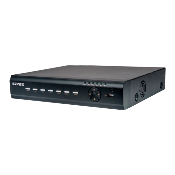
- Page 1 Manuale per il collegamento e l’uso Installation and operation manual 46540.F04 46540.F08 DVR AHD 4/8 canali 1080P AHD DVR 1080p 4/8 channel...
-
Page 2: Table Of Contents
Sommario Introduzione ..........................................2 Presentazione del DVR ......................................... 2 Funzioni principali ......................................... 2 Telecomando ..........................................4 Controllo con il mouse ........................................4 2.1.1 Collegamento del mouse ......................................4 2.1.2 Utilizzo del mouse ......................................... 4 Istruzioni per le funzioni base ....................................5 Accensione/Spegnimento ...................................... - Page 3 9.1.6 Informazioni sulla registrazione ....................................31 9.1.7 QRCODE .............................................31 Gestione disco ..........................................32 Upgrade ............................................32 Logoff ............................................32 Sorveglianza in remoto ......................................32 10.1 Sorveglianza in remoto con NAT ....................................32 10.1.1 Settaggio NAT ..........................................32 10.1.2 Accesso NAT ..........................................33 10.2 Sorveglianza in remoto da Internet Explorer via LAN e WAN ............................33 10.2.1 Tramite LAN ..........................................33 10.2.2 Tramite WAN ..........................................33 10.3...
-
Page 4: Introduzione
Supporta la cattura di immagini e la regolazione del colore in remoto • Supporta la ricerca in remoto per ora ed evento e la riproduzione del canale con la cattura di immagini • Supporta il controllo PTZ in remoto con preimpostazioni e avanzamenteo automatico • Supporta la configurazione totale dei menu in remoto, con la modifica di tutti i parametri del DVR in remoto • Supporta la sorveglianza attraverso dispositivi mobili quali iPhone e sistemi operativi Android e Blackberry • Supporta CVM/Elvox per gestire più dispositivi su Internet... - Page 5 Connettersi al mouse USB, o un dispositivo di memorizzazione USB Pannello posteriore ALARM OUT AUDIO IN AUDIO OUT ALARM IN RS485 Fig. 1 DC12V HDMI AHD VIDEO IN CVBS 46540.F04 ALARM OUT ALARM IN AUDIO Fig. 2 AUDIO IN CVBS HDMI DC12V AHD VIDEO IN RS485 46540.F08...
-
Page 6: Telecomando
2 Telecomando Utilizza due batterie AAA. 1. Aprire il coperchio del vano batterie. 2. Inserire le batterie. Fare attenzione alla polarità (+ e -). 3. Riposizionare il coperchio del vano batterie. Pulsante Funzione Consente di attivare manualmente la registrazione. Search Accede al modo di ricerca. MENU Accede al menu. Exit Esce dalla schermata corrente. ENTER Conferma la scelta o la configurazione. Pulsanti di direzione Spostano il cursore durante la configurazione. -
Page 7: Istruzioni Per Le Funzioni Base
Istruzioni per le funzioni base Accensione/Spegnimento Prima di accendere l'unità assicurarsi che tutte le connessioni siano in ordine. 3.1.1 Accensione 1. Collegare l'apparecchio all'alimentazione di rete. 2. Il dispositivo si avvia e il LED di alimentazione diventa blu. 3. Viene visualizzata una finestra con la procedura guidata in cui sono indicate le informazioni sul fuso orario, l'impostazione dell'ora,la configurazione di rete, la configurazione di registrazione e la gestione del disco. L'utente può eseguire la configurazione in questa schermata facendo riferimento alla proce- dura di configurazione descritta nei capitoli corrispondenti. Se si preferisce non utilizzare la procedura guidata, fare clic sul pulsante Exit per uscire. 3.1.2 Spegnimento L'utente può spegnere il dispositivo con il telecomando, la tastiera e il mouse. 1. Andare al Menu e selezionare l'icona "Spegnimento" per aprire la finestra di spegnimento. 2. Fare clic su OK. Dopo qualche istante l'unità si spegne. 3. -
Page 8: Riproduzione Live
Simbolo Significato Verde Registrazione manuale Giallo Registrazione per rilevamento movimento Registrazione programmata 3.4 Riproduzione Live Fare clic sul pulsante per riprodurre la registrazione. Far riferimento alla Fig. 3-3. Utilizzare i pulsanti sullo schermo per eseguire le varie funzioni. Fig. 3-3 Riproduzione Live 4. Guida alla configurazione del menu principale Fare clic con il pulsante destro del mouse o premere il pulsante FN sul pannello anteriore per visualizzare la barra dei comandi in fondo alla schermata. Far riferimento alla Fig. -
Page 9: Configurazione Di Base
4.1 Configurazione di base La configurazione di base comprende tre sottomenu: sistema, data e ora e DST. 4.1.1 Sistema 1. Andare a Menu Setup Basic System. Far riferimento alla Fig. 4-3. Fig. 4-3 Configurazione di base - Sistema 2. In questa schermata è possibile impostare il nome del dispositivo, l'ID dispositivo, il formato video, il numero massimo di utenti della rete, la risoluzione VGA/HDMI, la lingua e così via. Le definizioni dei singoli parametri sono le seguenti: Device Name (Nome dispositivo): Il nome del dispositivo. Può essere visualizzato sul lato client o CMS/NVMS per aiutare l'utente a riconoscere il dispo- sitivo in remoto. Device ID (ID dispositivo): L'ID dispositivo si utilizza per mappare il DVR con la tastiera. Video Format (Formato video): Due modi: PAL e NTSC. È possibile selezionare il formato video in base a quello della telecamera. Password Check (Richiedi password): se questa opzione è attivata, l'utente deve inserire nome utente e password per eseguire le operazioni corrispon- denti. -
Page 10: Dst
2. Consente di impostare il formato data, il formato ora, il fuso orario dell'interfaccia: selezionare la casella "sync time with NTP server" (sincronizza l'ora con server NTP) per aggiornare il sistema in base ai dati del server NTP. È inoltre possibile impostare manualmente la data del sistema. 3. Fare clic sul pulsante "Apply" (Applica) per salvare le impostazioni. 4.1.3 DST 1. Andare a Menu Setup Basic DST. Far riferimento alla Fig. 4-5. 2. In questa schermata è possibile attivare l'ora legale, la differenza di fuso orario, il modo, mese/settimana/data di inizio e di fine, ecc. 3. Fare clic sul pulsante "Apply" (Applica) per salvare le impostazioni. Fig. 4-5 Configurazione di base - DST 4.2 Configurazione Live La configurazione Live include quattro sottomenu: Live, monitor principale, spot e maschera. 4.2.1 Live In questa schermata è possibile impostare il nome della telecamera e regolare i colori. Per impostare il nome della telecamera: 1. Andare a Menu Setup Live. Far riferimento alla Fig. 4-6. Fig. 4-6 Configurazione Live - Live 2. -
Page 11: Monitor Principale
4.2.2 Monitor principale Le impostazioni del monitor principale consentono di impostare la sequenza della telecamera in modo visualizzazione Live. Per configurare il monitor principale seguire questa procedura: 1. Andare a Menu Setup Live Main Monitor. Far riferimento alla Fig. 4-7. Fig. 4-7 Configurazione Live - Monitor principale 2. Selezionare il canale e il modo di visualizzazione. 3. Selezionare un valore per il tempo di visualizzazione di ogni schermo nella casella Dwell Time. Fare clic sul pulsante per impostare i gruppi di canali precedenti delle immagini Dwell. Fare clic sul pulsante per impostare i gruppi di canali successivi delle immagini Dwell. -
Page 12: Maschera
4.2.3 Maschera Se vi sono elementi che non si desidera siano visibili nell'immagine Live, è possibile configurare una maschera. È possibile mascherare fino a tre aree per canale. Per impostare l'area da mascherare: 1. Andare a Menu Setup Live Mask. Fig. 4-8 Configurazione Live - Maschera 2. Fare clic sul pulsante "Setting" (Impostazioni) per passare all'immagine Live. 3. Premere il pulsante sinistro del mouse e trascinare il cursore per impostare l'area da mascherare, come illustrato sotto. 4. -
Page 13: Attivazione
4.3.1 Attivazione 1. Andare a Menu Setup Live Enable. Far riferimento alla Fig. 4-10. Fig. 4-10 Configurazione della registrazione - Attivazione Parametro Significato Record (Registrazione) Attiva/disattiva la registrazione per il canale selezionato Audio Attiva/disattiva la registrazione audio per il canale selezionato 2. Selezionare le caselle registrazione e audio. 3. Selezionare "All" (Tutti) per impostare gli stessi valori per tutti i canali. 4.3.2 Bit Rate di registrazione 1. -
Page 14: Tempo
4.3.3 Tempo 1. Andare a Menu Setup Record Time per impostare il tempo di registrazione. Far riferimento alla Fig. 4-12. 2. Impostare il tempo di registrazione pre-allarme e post-allarme. Selezionare "All" (Tutti) per impostare gli stessi valori per tutti i canali. Pre-alarm Record Time (Tempo di registrazione pre allarme): impostare il tempo, in secondi, in cui deve essere eseguita la registrazione prima che inizi la registrazione vera e propria. -
Page 15: Riciclo Della Registrazione
Prima del trascinamento Dopo il trascinamento 3. Selezionare "All" (Tutti) per impostare gli stessi valori per tutti i canali. 4.3.5 Riciclo della registrazione Questa opzione consente di sovrascrivere i dati dell'HDD (riciclo) quando è pieno. Se attivata, quando tutto lo spazio dell'HDD è stato utilizzato, il sistema elimina automaticamente le vecchie registrazioni e ricicla lo spazio liberato. La procedura di impostazione è la seguente: 1. -
Page 16: Programmazione Movimento
Fig. 4-15 Programmazione - Programmazione settimanale 4.4.2 Programmazione movimento Questa scheda consente di impostare la programmazione della registrazione attivata dal movimento. La procedura di impostazione è la seguente: 1. Andare a Menu Setup Schedule scheda Motion. 2. La procedura di configurazione della registrazione attivata dal movimento è analoga a quella di configurazione della programmazione normale. Far riferi- mento al paragrafo 4.4.1 Programmazione per maggiori dettagli. Nota: La programmazione predefinita della registrazione attivata dal movimento è... -
Page 17: Allarme Movimento
6 -Fare clic sul pulsante “Setting” (Impostazione) per attivare la visualizzazione di una finestra di dialogo come illustrato di seguito. Buzzer (Segnalatore acustico): Se questa opzione è selezionata, in caso di allarme viene attivato il segnalatore acustico locale. Show Full Screen (Mostra a tutto schermo): Se questa opzione è selezionata, in caso di allarme il canale scelto viene visualizzato sul monitor. To Alarm Out (All’uscita allarme): Se selezionata, questa opzione attiva l’uscita relè esterna in caso di allarme. Email: Se questa opzione è selezionata, in caso di allarme basato sul sensore proveniente dall’ingresso specificato, il DVR ibrido AHD invia una email di avviso a un indirizzo di posta elettronica preimpostato. -
Page 18: Perdita Video
3 - La procedura di configurazione dell’attivazione dell’allarme di movimento è analoga a quella in “Alarm Handling” (Gestione allarmi) (per ulteriori dettagli, vedere l’impostazione Sensor Alarm Handling). 4 - Una volta fatto clic sul pulsante Area, viene visualizzata una finestra di dialogo come quella illustrata di seguito 5 - Nella schermata Area è possibile trascinare il cursore sulla barra di scorrimento per impostare il valore della sensibilità (da 1 a 8) A un valore maggiore corrisponde una maggiore sensibilità al movimento. Dal momento che la sensibilità è influenzata dal colore e dall’ora (giorno o notte) è possibile impostare il valore in base alle effettive condizioni. Fare clic con il pulsante sinistro del mouse sulla griglia e trascinare per eliminare l’area. Fare clic sull’icona per impostare tutta l’area come area di rilevamento. Fare clic sull’icona per cancellare l’area di rilevamento impostata. Fare clic sull’icona per pro- vare la sensibilità in base alle condizioni locali. Quando viene rilevato il movimento, appare un’icona. Fare clic sull’icona per salvare l’impostazione. Fare clic sull’icona per uscire dalla schermata corrente. Nota: Prima di impostare il campo di rilevamento del movimento si consiglia di fare clic sull’icona per cancellare l’impostazione del campo esistente ed eseguire di nuovo l’impostazione. -
Page 19: Uscita Allarme
5.4 Other Alarm (Altro allarme) In questa scheda è possibile configurare l’allarme per Disk Full (Disco pieno), IP Conflict (Conflitto IP), l’evento Disconnect (Disconnessione), Disk Attenua- tion (Riduzione disco) o Disk Lost (Perdita disco). 1 - Andare in Main Menu Setup Alarm Other Alarm. 2 - Utilizzare il menu a discesa e selezionare l’evento o l’allarme. 3 - Selezionare le opzioni di attivazione desiderate. Se l’evento selezionato è “Disk Full” (Disco pieno), utilizzare la casella a discesa “Disk Shortage Alarm” (Allarme disco insufficiente) per scegliere un valore di soglia per lo spazio rimanente su HDD. -
Page 20: Configurazione Rete
2 - Immettere il nome relè e selezionare il tempo di attesa. 3 - Andare alla scheda “Schedule” (Programmazione). La procedura di impostazione della programmazione per l’uscita allarme è analoga a quella di confi- gurazione della programmazione normale (per maggiori informazioni vedere il paragrafo 6.3, Programmazione della registrazione). Per configurare il segnalatore acustico: 4 - Andare in Main Menu Setup Alarm Alarm Out Buzzer. 5 - Selezionare la casella Buzzer (Segnalatore acustico) e impostare il tempo di attesa dell’allarme. In tal modo, quando il sistema entra in allarme viene attivato il segnalatore acustico. -
Page 21: Flusso Secondario
6.2 Flusso secondario Per impostare il flusso secondario: 1. Andare a Menu Setup Live Sub Stream. Far riferimento alla Fig. 6-2. 2. Selezionare fps, risoluzione, qualità, codifica e bitrate massimo. 3. Selezionare "All" (Tutti) per impostare gli stessi valori per tutti i canali. Fig. 6-2 Configurazione di rete - Flusso secondario Parametro Significato Valori consentiti: 1-25 Resolution (Risoluzione) Supporto CIF Quality (Qualità) La qualità dell'immagine del client ad un valore maggiore corrisponde una maggiore nitidezza dell'immagine registrata. -
Page 22: Server
6.4 Server Questa funzione viene utilizzata principalmente per connettere il server ECMS/NVMS. La procedura di impostazione è la seguente: 1. Nella schermata Server, selezionare "Enable" (Attiva) come indicato nella Fig. 6-4. Fig. 6-4 Configurazione di rete - Server 2. Controllare l'indirizzo IP e la porta del server di trasferimento nel server ECMS/NVMS. La porta di server predefinita per l'auto segnalazione è 2009. Se viene modificata, andare alla schermata del server di trasferimento per controllare. 3. Quando viene aggiunto un nuovo dispositivo, abilitare l'auto segnalazione nel server ECMS/NVMS. Inserire un ID dispositivo e immettere le restanti informazioni relative al dispositivo nel server ECMS/NVMS. 4. Inserire l'IP server suddetto, la porta server e l'ID dispositivo nella schermata del server. Fare clic sul pulsante "Apply" (Applica) per salvare le impostazioni. Il sistema ECMS/NVMS ora connetterà automaticamente il dispositivo. -
Page 23: Altre Impostazioni
6.6 Altre impostazioni Se il DVR è configurato per utilizzare il PPPoE come connessione di rete predefinita, è possibile configurare congiuntamente il DDNS. La procedura di impostazione è la seguente: 1. Attivare il server DDNS. 2. Selezionare il server DDNS. 3. Inserire nome utente, password, nome del dominio host del sito web registrato. 4. Fare clic sul pulsante "Test" per verificare l'esattezza delle informazioni. 5. Fare clic sul pulsante "Apply" (Applica) per salvare le impostazioni. Fig. 6-6 Configurazione di rete - Altre impostazioni Nota: Il nome di dominio selezionato dall'utente è un nome di dominio di banda del DVR. L'utente deve effettuare il login al sito del provider del server per registrare un nome utente e una password, quindi fare richiesta di un nome di dominio online. - Page 24 2. Creare un nome di dominio. 3. Quando la richiesta del nome di dominio sarà stata finalizzata, il nome di dominio sarà visualizzato nell'elenco. Impostazione DVR Collegare il DVR al client di rete. 1. Andare a Main menu Setup Network Other Settings, selezionare la casella DDNS, selezionare “dvrdydns” nella casella di elenco a discesa DDNS Server e inserire nome utente e password. 2. Andare alla schermata di configurazione del router per mappare la porta server e l'indirizzo IP (se è attivata la funzione UPnP questo passaggio può essere saltato). Fare clic sul pulsante "Save" (Salva) per salvare le impostazioni. 3. Aprire Internet Explorer e inserire il nome del dominio registrato "http://www.xxx.dvrdydns.com", collegarsi al client DVR. È anche possibile registrare velocemente il nome di dominio in questa schermata.
-
Page 25: Configurazione Della Gestione Utente
6.7 Configurazione della gestione utente In questa scheda è possibile aggiungere utenti normali o avanzati. Per aggiungere un utente e assegnargli le autorizzazioni: 1. Andare a Menu Setup Users. Far riferimento alla Fig. 6-8. Fig. 6.-8 Configurazione gestione utente 2. Fare clic sul pulsante "Add" (Aggiungi) per visualizzare la finestra di dialogo illustrata nella Fig. 6-9. Fig. 6-9 Aggiungi - Generale 3. Nella scheda "General" (Generale) inserire nome utente e password e selezionare il tipo di utente. È anche possibile selezionare la casella "Binding PC MAC Address" (Indirizzo MAC vincolante per il PC) e inserire tale indirizzo. 4. Fare clic sul pulsante "OK" per salvare le impostazioni. Nota: Se il valore predefinito per l'indirizzo MAC vincolante del PC è... -
Page 26: Configurazione Ptz
Per eliminare un utente: 1. Andare a Menu Setup Users 2. Selezionare gli utenti aggiunti che si desidera eliminare e fare clic sul pulsante "Delete" (Elimina). Per modificare un utente: 1. Andare a Menu Setup Users 2. Selezionare gli utenti aggiunti che si desidera modificare e fare clic sul pulsante "Modify" (Modifica) per eseguire l'operazione pertinente. Per cambiare la password utente: 1. Andare a Menu Setup Users 2. Selezionare gli utenti aggiunti per cui si desidera modificare la password e fare clic sul pulsante "Change Password" (Cambia password). - Page 27 2. Nella scheda di configurazione delle preimpostazioni, inserire il nome della preimpostazione quindi fare clic sul pulsante "Setting" (Impostazione) corri- spondente alla preimpostazione. Fig. 6-14 Configurazione preimpostazioni 3. Controllare la telecamera dome attraverso la rotazione verso l'alto, in alto a destra, in alto a sinistra, verso il basso, in basso a destra e in basso a sinistra, regolare la velocità di rotazione, il valore di zoom, la lunghezza della focale e l'apertura del diaframma della telecamera dome. 4. Selezionare il numero di serie della preimpostazione. Fare clic sul pulsante per attivare il tergicristalli del PTZ e su per accendere la luce del PTZ. Nota: il dispositivo PTZ deve supportare i pulsanti del tergicristalli e della luce, i due pulsanti sono disponibili solo quando si seleziona PELCOP o PELCOD.
-
Page 28: Configurazione Avanzata
Fig 6-17 Configurare il percorso 6.9 Configurazione avanzata La configurazione avanzata comprende tre sottomenu: reset, imposta/esporta ed elenco blocca/consenti. 6.9.1 Reset Ripristina le impostazioni predefinite di fabbrica del dispositivo. 6.9.2 Importa/Esporta Consente di esportare i file di dati in dispositivi di archiviazione mobili con funzione di backup e quindi importare i file di dati specificati dal dispositivo di archiviazione mobile al DVR. 6.9.3 Elenco Blocca/Consenti In questa schermata un utente autorizzato può impedire o consentire ad altri utenti di computer compresi in uno specifico intervallo di indirizzo IP di accedere al DVR. Se, ad esempio, un utente amministratore desidera che gli utenti in un intervallo di indirizzo IP compreso tra 192.168.000.002 e 192.168.000.004 non accedano al DVR, può selezionare l’opzione “Block list” (Elenco bloccati) e immettere tale intervallo di indirizzo IP. Se è necessario che gli utenti in un determinato intervallo di indirizzo IP accedano al DVR, l’amministratore può selezionare “Allow List” (Elenco consentiti) e inserire i valori desiderati. Fig. - Page 29 Se la telecamera IP non è nella stessa rete locale, è possibile selezionare il dispositivo e fare clic su “Setup” (Configurazione) per modificare l'indirizzo IP del dispositivo cercato. Nota: Se la rete di telecamere IP e il DVR ibrido AHD sono in una rete locale, il loro indirizzo IP deve rientrare nel stesso segmento di rete. Ad esempio: Se l'indirizzo IP del DVR ibrido AHD è 192.168.011.007, l'indirizzo IP della telecamera IP deve essere 192.168.011.XXX. 3 - Selezionare i dispositivi cercati e fare clic sul pulsante “OK” per tornare alla schermata precedente. Fare clic sul pulsante “Apply” (Applica), dopodiché i dispositivi aggiunti verranno elencati nella schermata di gestione dei dispositivi. Lo stato “Connected” (Connesso) indica che la connessione del disposi- tivo è...
-
Page 30: Roi
7.2 ROI È possibile impostare aree ROI (regione di interesse). L’area ROI selezionata appare più chiara rispetto alle altre aree, in particolare a un bit rate basso. È possibile utilizzare questa funzione dopo avere aggiunto le telecamere IP. Andare a Main Menu Setup Live ROI. 2- Fare clic sul tasto Setting per visualizzare la finestra di dialogo seguente. 3- Selezionare “enable”. Trascinare il mouse per impostare l’area ROI. È possibile impostare fino a 3 aree ROI. 4- Trascinare il cursore a slitta per impostare il valore di sensibilità (0-9). A un valore maggiore corrisponde una maggiore sensibilità al movimento. Dal momento che la sensibilità è influenzata dal colore e dall’ora (giorno o notte) è possibile impostare il valore in base alle condizioni locali. Fare clic sull’icona per salvare le impostazioni. Fare clic sull’icona per uscire dalla schermata corrente. 7.3 Impostazioni della telecamera IP Andare a Main Menu Setup Live Cam Parameter. Fare clic sul tasto Setting per visualizzare la finestra di dialogo seguente. -
Page 31: Ricerca Evento
Per impostare il backup per un periodo specifico nella schermata di riproduzione: Selezionare l'ora di inizio trascinando il cursore a slitta e fare clic sull'icona . Selezionare quindi l'ora di fine e fare clic di nuovo sull'icona per confer- mare il periodo di registrazione. Quindi fare clic sull'icona per eseguire il backup della registrazione nel periodo impostato. 8.2 Ricerca evento 1. Andare a Menu Search pulsante Event Search. Far riferimento alla Fig. 8-2. Fig. 8-2 Configurazione della ricerca - Ricerca evento 2. Selezionare la data e i canali sul lato destro. Se i dati hanno il bordo evidenziato significa che sono presenti dei dati. -
Page 32: Backup
Fig. 8-4 Configurazione della ricerca - Immagine Lock (Blocca): Selezionare l'immagine e fare clic sul pulsante Lock per bloccare l'immagine. Save (Salva): Fare clic sul pulsante "Save" per copiare l'immagine sull'HDD. Save All (Salva tutti): Fare clic sul pulsante "Save all" per copiare tutte le immagini sull'HDD. 8.5 Backup Questa unità supporta il backup con un'unità USB flash. È inoltre possibile eseguire il backup da Internet Explorer via Internet (vedere il paragrafo 10.3.2 Backup in remoto). 1. Andare alla configurazione del backup. Far riferimento alla Fig. 8-5. 2. Impostare l'ora di inizio e di fine, selezionare i canali e fare clic sul pulsante Search (Cerca) per visualizzare i dati cercati nella casella di riepilogo dei dati di backup. Fig. 8-5 Configurazione del backup 3. Selezionare un file o selezionare la casella “All” (Tutti) per selezionare tutti i file di dati. Fare clic sul pulsante Backup per visualizzare la finestra delle informazioni sul backup. -
Page 33: Gestione Del Dvr
Gestione del DVR 9.1 Controllo delle informazioni di sistema La verifica delle impostazioni di sistema comprende sei sottomenu: sistema, evento, log, rete, utenti online e registrazione. 9.1.1 Informazioni di sistema In questa schermata è possibile controllare la versione dell'hardware, la versione della MCU, la versione del kernel, l'ID dispositivo e così via. 9.1.2 Informazioni sull'evento In questa schermata è possibile cercare eventi quali il movimento o la perdita del segnale video. Questa utility fornisce un'interfaccia in cui è possibile esegui- re una ricerca per data e per canale. Il rapporto può essere salvato su una memoria USB in formato html utilizzando il pulsante Export (Esporta). 9.1.3 Informazioni sul log In questa schermata è possibile eseguire una ricerca nei log pertinenti per data e per evento, inclusi Operation (Funzionamento), Setup (Configurazione), Playback (Riproduzione), Backup, Search (Ricerca), Check Information (Controlla informazioni) ed Error (Errore). Il rapporto può essere salvato su una me- moria USB in formato html utilizzando il pulsante Export (Esporta). 9.1.4 Informazioni sulla rete In questa schermata è possibile selezionare i parametri di rete pertinenti. -
Page 34: Gestione Disco
Fig. 9-1.A Infromazioni per la configurazione In questa interfaccia è possibile leggere il codice QRCODE con un telefono cellulare. Fare riferimento alla Fig. 9-1.B. Fig. 9-1.B Configurazione informazioni Appena la scansione viene eseguita, l’indirizzo MAC del DVR / NVR compare sul campo “Server” su Superlive PRO Inserire nome utente e password del DVR / NVR Default: User: admin Password: 123456 Premere il pulsante “Login” sull’interfaccia SUPERLIVE PRO ed il telefono cellulare è connesso al DVR / NVR 9.2 Gestione disco Formattazione del disco 1 - Andare alla scheda Disk management (Gestione disco). Nota: prima della registrazione formattare il disco rigido. 2. Fare clic sul pulsante “Refresh” per aggiornare le informazioni sul disco nella casella di riepilogo. 3. Selezionare un disco rigido e fare clic sul pulsante Format (Formatta) per avviare la formattazione. Nota: La formattazione cancella tutta i file registrati sul disco rigido. -
Page 35: Accesso Nat
10.1.2 Accesso NAT Dopo aver completato la configurazione del NAT, è possibile accedere al server NAT sul PC remoto (immettere http://www.autonat.com per accedere al client Internet Explorer). Se è la prima volta che si accede al NAT, la rete scarica automaticamente i controlli ActiveX. Nota: il client WEB deve trovarsi nella rete remota. Non può trovarsi nella stessa rete locale di quella dell’NVR, altrimenti l’accesso restituirà un errore. Se si riscontrano problemi relativi al download e all’installazione dei controlli ActiveX, far riferimento alle FAQ, domande frequenti, D8. Dopo aver installato i controlli ActiveX, viene visualizzata la finestra di login. Serial No: l’indirizzo MAC dell’NVR. (Andare a Main Menu Information Network per verificare l’indirizzo MAC dell’NVR). User Name (nome utente): Il nome utente di accesso dell’NVR. Il nome utente predefinito è admin. -
Page 36: Tramite Lan
3. Selezionare "Apri in modalità 32-bit". 10.3.1 Tramite LAN 1. Dopo aver avviato il computer Apple, fare clic sull'icona della mela. Verrà visualizzata la seguente finestra: Selezionare "Preferenze di sistema" "Internet e Wireless” "Rete". 2. Accedere all'interfaccia di rete e fare clic su "Connessioni Ethernet" per verificare la connessione a Internet del computer Apple. 3. Prendere nota dell'indirizzo IP, la Subnet Mask ecc., quindi, nel DVR andare a Main Menu Setup Network per inserire manualmente l'indirizzo IP, la Subnet Mask e il Gateway copiati dalla configurazione del computer. Il segmento di rete deve essere uguale a quello del computer. Se si utilizza il pro- tocollo DHCP, attivarlo sia nel DVR sia nel router. 4. Dopo aver inserito le suddette informazioni è possibile inserire l'IP della LAN e la porta HTTP in Safari. Ad esempio, inserire: http://192.168.1.100:81 (nell'esempio 192.168.1.100 è l'IP della LAN del DVR, 81 è la porta HTTP del DVR) e fare clic sul pulsante " ". Il browser scarica il controllo ActiveX come illustrato di seguito: 5. -
Page 37: Tramite Wan
Inserire nome utente e password del computer Apple quindi fare clic su "OK" per installare il controllo ActiveX. 6. Al termine dell'installazione del controllo ActiveX, uscire da Safari. Fare clic con il pulsante destro sull'icona Safari sul desktop e selezionare "Esci" per chiudere il browser. Riavviare Safari. Inserire l'indirizzo IP e la porta HTTP per accedere alla schermata di accesso del DVR. 10.3.2 Tramite WAN Sono disponibili due modi per collegare il DVR a Internet. 1. Collegare il DVR a Internet tramite il router o il server virtuale 1. Le configurazioni di rete sono le stesse descritte dal passaggio 1 al passaggio 4 del punto 1 della procedura per la sorveglianza in remoto da Internet Explorer su WAN. - Page 38 Scatto di istantanee Fare clic sull'icona "Snap" per catturare automaticamente fermo immagine e salvarli sul computer. In Remote Preview interface Configuration Local, è possibile impostare un percorso di salvataggio per le istantanee. Regolazione del colore Trascinare il cursore sulla barra per regolare luminosità, contrasto, tonalità cromatica e saturazione. Fare clic su Predefinito per ripristinare i valori originali. Pulsanti Descrizione Trascinare il cursore a slitta per regolare la luminosità del canale. Trascinare il cursore a slitta per regolare il contrasto del canale. Trascinare il cursore a slitta per regolare la saturazione del canale.
-
Page 39: Riproduzione E Backup In Remoto
Fare clic con il pulsante destro del mouse nell'interfaccia Live. Verrà visualizzato un menu a discesa. Fig. 10-2 Menu attivato con il pulsante destro Stream (Flusso): Questo DVR supporta il flusso principale e il flusso secondario. Il flusso principale ha un frame rate più elevato, massimo 25FPS (PAL)/30FPS (NTSC) per ogni canale e richiede una maggiore larghezza di banda della rete. Il flusso secondario ha un frame rate più basso, massimo 6FPS (PAL)/7FPS (NTSC) per ogni canale e richiede una minore larghezza di banda della rete. Selezionare pertanto il flusso in base alla larghezza di banda disponibile. All to master/sub stream (Tutti su flusso principale/secondario): imposta tutti i canali sul flusso principale o secondario. Enable audio (Attiva audio): attiva o disattiva l'audio. Full screen (Schermo intero): In modo schermo intero l'anteprima occupa tutto lo schermo e la barra degli strumenti non è visibile. Fare doppio clic con il pulsante sinistro o fare clic con il pulsante destro per uscire. Zoom in (Zoom avanti): ingrandimento elettronico dell'immagine su canale singolo. - Page 40 Fig. 10-4 Schermata di ricerca cronologica 6. Fare clic nell'interfaccia sui pulsanti relativi alle varie operazioni, quali FF (Avanti veloce), pausa, cambia modo canale, ecc. Far riferimento alla Fig. 10-5: Fig. 10-5 Riproduzione della ricerca cronologica...
- Page 41 Ricerca per evento: 1. Andare a Search Event Search. Far riferimento alla Fig. 10-6. 2. Fare clic sulla data evidenziata e selezionare i canali di registrazione. 3. Selezionare la casella di controllo del tipo di evento: Motion (Movimento). 4. Fare clic sul pulsante "Search" (Cerca). 5.
-
Page 42: Configurazione Del Sistema In Remoto
Fig. 10-8 Interfaccia di backup in remoto 1. Selezionare i canali, impostare l'ora di inizio e di fine, quindi fare clic sul pulsante "Search" (Cerca) per visualizzare le informazioni sul file nella casella di riepilogo dei file. 2. Selezionare i file di backup e fare clic sul pulsante "Browse" (Sfoglia) per specificare un percorso in cui salvarli. Fare clic sul pulsante "Backup" per avviare il backup. I file di backup vengono salvati sul computer dell'utente. 10.6 Configurazione del sistema in remoto È possibile configurare il dispositivo in remoto per le seguenti funzioni: configurazione base, configurazione Live, configurazione delle registrazioni, configu- razione della programmazione, configurazione dell'allarme, configurazione della rete e configurazione dell'utente. Selezionare un'opzione dall'elenco sulla sinistra, quindi impostare i parametri relativi. La configurazione può essere eseguita da un solo utente per volta. Fare clic sulla scheda Config (Configurazio- ne) per visualizzare la schermata illustrata di seguito. L'elenco dei sottomenu e le opzioni di ciascun menu sono analoghi a quelli del DVR. Per maggiori dettagli, far riferimento al Capitolo 4 - Guida alla configu- razione del menu principale. Fig. 10-9 Configurazione dei menu in remoto 10.7 Strumenti Fare clic sulla scheda degli strumenti per accedere allo strumento Disk Management (Gestione disco). L'utente può visualizzare lo stato delle unità a disco rigido, visualizzare/modificare le proprietà di lettura/scrittura e formattare le unità a disco rigido. 10.8 Gestione in remoto La scheda Info fornisce un'interfaccia basata sul Web per accedere alle informazioni generali relative alle impostazioni del DVR. L'interfaccia include cinque sottomenu: System (Sistema) Event (Evento), Log, Network (Rete) e Online users (Utenti online). Nota: Le funzioni di sorveglianza in remoto su Internet Explorer e su computer Apple potrebbero essere leggermente diverse tra loro. In questo documento viene descritto solo l'accesso remoto da Internet Explorer. -
Page 43: Appendice A Domande Frequenti (Faq)
Appendice A FAQ (Domande frequenti) D1. Perché il DVR non si accende dopo aver collegato l'alimentazione? L'alimentatore potrebbe essere danneggiato. Sostituire con un alimentatore nuovo. La potenza dell'alimentatore potrebbe non essere sufficiente per azionare il DVR. Utilizzare l'alimentatore in dotazione con il DVR. Potrebbe trattarsi di un problema dell'hardware. D2. Non viene visualizzato alcun menu ma solo l'immagine Live. Controllare che il monitor sia collegato all'uscita video principale e non all'uscita spot. È possibile collegare il monitor alla porta VGA mentre il DVR può essere impostato per il collegamento all'uscita BNC o viceversa. Premere a lungo il tasto Fn/ESC per commutare tra i due modi di uscita. D3. Il LED del DVR si accende ma non si vede niente. La potenza dell'alimentatore potrebbe non essere sufficiente per azionare il DVR. Utilizzare l'alimentatore in dotazione con il DVR. Potrebbe essere un problema di cablaggio. Controllare i collegamenti. Controllare le impostazioni del monitor. D4. Perché non sono visualizzate le immagini di alcuni o di tutti i canali del DVR? Potrebbe essere un problema di cablaggio. Controllare i cavi e le porte delle telecamere e del DVR. - Page 44 Fig. 1 Fig. 2 D9: Sul DVR è sempre visualizzato il messaggio "please wait..." (attendere...). a. Il cavo di alimentazione e il cavo dati dell'HDD potrebbero non essere collegati correttamente. Controllare le connessioni dell'HDD. b. È inoltre possibile che sia stato forzato l'arresto del DVR a causa di un settore danneggiato dell'HDD che ha provocato un arresto del sistema. Per verificare utilizzare un HDD del cui corretto funzionamento si è certi, oppure provare a formattare l'HDD esistente. D10: Come faccio per immettere la password e i numeri? Fai clic sulla casella di inserimento della password per visualizzare una tastiera virtuale. Selezionare i caratteri da inserire (la password preimpostata è 123456) oppure utilizzare i tasti sul pannello anteriore o i tasti del telecomando. D11: Il disco rigido è stato rilevato come nuovo dispositivo anche se era stato utilizzato su un DVR dello stesso modello. È necessario format- tarlo prima dell'uso? È possibile trasferire un HDD da un DVR a un altro a condizione che i due DVR siano dello stesso modello e che l'HDD che viene trasferito sia utilizzato come unico disco rigido nel nuovo DVR. Tuttavia, nei casi un cui il nuovo DVR contenga già un HDD, il disco rigido che viene trasferito dovrà essere for- mattato. Il trasferimento di un HDD da un DVR a un altro è comunque generalmente sconsigliabile.
- Page 45 F are clic con il pulsante destro del mouse su Internet Explorer (far riferimento alla figura seguente) e selezionare Esegui come amministratore. D14. Come si riproduce il file di backup? Inserire il dispositivo USB su cui sono salvati i file di backup nella porta USB del PC. Se i file sono salvati in formato DVR significa che il lettore di backup è già stato scaricato prima di eseguire il backup. Fare quindi doppio clic per aprire il disco USB e trovare i file di backup e il lettore di backup. Fare doppio clic sull'icona per installare il lettore di backup. Al termine dell'installazione, aprire il lettore e fare clic sul pulsante "Open Path" (Apri percorso) per apri- re il file di backup. Fare clic sul pulsante per riprodurre il file di backup. Fare doppio clic sull'immagine e quindi fare clic con il pulsante destro del mouse per attivare l'audio. Se si salvano i file di backup in formato AVI è possibile aprire direttamente il file utilizzando il media player che supporta tale formato.
-
Page 46: Calcolo Della Capacità Di Registrazione
Appendice B Calcolo della capacità di registrazione Gli utenti possono calcolare la dimensione del disco rigido in base al tempo di salvataggio e alle impostazioni di registrazione del DVR. Il DVR utilizza il bit rate video fisso. Di seguito sono riportati i dati alle diverse impostazioni. Risoluzione Frame Rate totale (FPS) Qualità video Bit Rate (kbps) Spazio utilizzato (MB/h) 720P 25 (PAL) / 30 (NTSC) Massima 6144 2700 Superiore 5420 2250 1080p 12 (PAL) / 15(NTSC) Media 4096 1800 Bassa 3072... -
Page 47: Specifiche
Caratteristiche tecniche Modello 46540.F04 46540.F08 Compressione Standard H.264 profilo alto Sistema Cortex A9 Sistema operativo Linux incorporato Ingresso BNC x 4 BNC x 8 Ingresso IP/ IPC x 1 / 6 Mbps IPC x 4 / 24Mbps Video larghezza di banda di accesso HDMI x 1:1920 x 1080 / VGA x 1:1920 x 1080... - Page 48 Table of Contents Introduction ..........................................48 DVR Introduction ......................................... 48 Main Features ..........................................48 Remote Controller ........................................50 2.1 Control with Mouse ........................................50 2.1.1 Connect Mouse ........................................... 50 2.1.2 Use Mouse ..........................................50 Basic Function Instruction ....................................... 51 3.1 Power On/Off ..........................................51 3.1.1 Power On ............................................
- Page 49 9.1.3 Log Information ........................................... 77 9.1.4 Network Information ........................................77 9.1.5 Online Information ........................................77 9.1.6 Record Information ........................................77 9.1.7 QRCODE ............................................ 77 Disk Management ........................................79 Upgrade ............................................79 Logoff ............................................79 Remote Surveillance ......................................... 79 10.1 IE Remote Surveillance by NAT ....................................79 10.1.1 NAT Settings ..........................................
-
Page 50: Introduction
Supports TCP/IP, DHCP, PPPoE, DDNS protocol • Supports NAT technology • Supports IE browser to do remote view • Supports QRCODE Scanning through mobile phone client • Supports setup client connection amount • Supports dual stream. Network stream is adjustable independently to fit the network bandwidth and environment • Supports picture snap and color adjustment in remote live • Supports remote time and event search, and channel playback with picture snap • Supports remote PTZ control with preset and auto cruise • Supports remote full menu setup, changing all the DVR parameters remotely • Supports mobile surveillance by phones with iPhone & Android OS • Supports CVM Elvox to manage multi devices on internet... - Page 51 Connect to USB mouse, or USB storage device Rear panel ALARM OUT AUDIO IN AUDIO OUT ALARM IN RS485 Fig. 1 DC12V HDMI AHD VIDEO IN CVBS 46540.F04 ALARM OUT ALARM IN AUDIO Fig. 2 AUDIO IN CVBS HDMI DC12V AHD VIDEO IN RS485 46540.F08...
-
Page 52: Remote Controller
2 Remote Controller It uses two AAA size batteries. - Open the battery cover of the remote controller. - Place batteries. Please take care the polarity (+ and -). - Replace the battery cover. Button Function Record manually Search To enter search mode. MEUN To enter menu. Exit To exit the current interface. ENTER To confirm the choice or setup. Direction button To move cursor in setup ZOOM To zoom in To set picture in picture To control playback. Play/Pause/Stop/Previous Section/Next Section/Rewind/Fast Forward... -
Page 53: Basic Function Instruction
Basic Function Instruction Power On/Off Before you power on the unit, please make sure all the connection is good. 3.1.1 Power On 1. Connect with the source power. 2. The device will boot and the power LED would turn blue. 3. A WIZARD window will pop up and show some information about time zone, time setup, network configuration, record configuration and disk manage- ment. User can set up here and refer to the concrete setup steps from the corresponding chapters. If users don’t want to set up Wizard, please click Exit button to exit. Press and hold FN/ESC key to switch the resolution of the VGA/ HDMI output. 3.1.2 Power Off User can power off the device by using remote controller, keyboard and mouse. 1. Go to Menu and then select “Shut Down” icon to pop up the Shut down window. 2. Click OK. Then the unit will power off after a while. 3. Disconnect the power. 3.2 Login User can login or log off the DVR system. Once logged off the user cannot do any other operation except changing the multi-screen display. Fig 3-1 Login Notice: The default user name and password is “admin” and 123456”. For complete operational steps for changing password, adding or deleting users, please refer to section 6.7 User Management Configuration. -
Page 54: Live Playback
3.4 Live Playback Click Playback button to playback the record. Refer to Fig 3-3. User can do complete operation by clicking the buttons on screen. Fig 3-3 Live Playback 4. Main Menu Setup Guide Click right mouse or press FN/ESC button on the front panel and then the control bar will display at the bottom of the screen. Refer to Fig 4-1. Color Audio Snap Playback Screen Mode Record Move Tool Main Menu E-Zoom Dwell Fig 4-1 Main Menu Toolbar Screen Mode: Click to choose screen mode. Dwell: Dwell means to display live images from different cameras in a sequence. The images may be displayed as a single channel or in a grid fashion from different cameras. Dwell mode is enabled only when the chosen display mode is not able to display all the available cameras. Color: If this button is enabled, you can adjust the color of live pictures. IPC: Click this button to set the parameters of the cameras. Please refer to 7.3 IP Camera settings for more details E-Zoom: Single channel large screen electronic amplification. Audio: Enable sound. -
Page 55: Basic Configuration
4.1 Basic Configuration Basic configuration includes three sub menus: system, date & time and DST. 4.1.1 System 1. Go to Menu Setup Basic System interface. Refer to Fig 4-3: Fig 4-3 Basic Configuration-System In this interface you can set up the device name, device ID, video format, max network users, VGA resolution, language and so on. The definitions for every parameters display as below: Device Name: The name of the device. It may display on the client end or CMS that help user to recognize the device remotely. Device ID: This ID is used to map the speed dome cameras. Video Format: Two modes: PAL and NTSC. User can select the video format according to that of camera. Password Check: If this option is enabled, the user would need to input the user name and the password for performing corresponding operations. Show System Time: If selected, the current time will be displayed during live monitoring. Max Online Users: To set the max number of concurrent user logins in the DVR. Video Output: The resolution of live display interface. Language: Set up the menu language. Note: After changing the language and video output, the device needs to login again. -
Page 56: Time & Date
2. Set the date format, time format, time zone in this interface; checkmark “sync time with NTP server” to refresh NTP server date. You can also adjust sy- stem date manually. 3. Click “Apply” button to save the setting. 4.1.3 DST 1. Go to Menu Setup Basic DST interface. Refer to Fig 4-5: 2. In this interface, enable daylight saving time, time offset, mode, start & end month/week/date, etc. 3. Click “Apply” button to save the setting. Fig 4-5 Basic Configuration-DST 4.2 Live Configuration Live configuration includes four submenus: live, main monitor, spot and mask. 4.2.1 Live In this interface, you can set up camera name and adjust colors. To set up camera name: 1. Go to Menu Setup Live. Refer to Fig 4-6: Fig 4-6 Live configuration - Live 2. A software keyboard will pop up by clicking camera name area. Click the letters and (or) digital numbers on the keyboard to input the name you want to display in live image. -
Page 57: Main Monitor
Live color adjustment 4.2.2 Main Monitor The main monitor settings allow you to set camera sequence in live display mode. Operate the following steps to set main monitor: 1. Go to Menu Setup Live Main Monitor interface. Refer to Fig 4-7: Fig 4-7 Live Configuration-Main Monitor 2. Select display mode and channel. 3. Select dwell time. Click button to set up the previous channel groups of dwell picture. Click button to set the latter channel groups of dwell picture. 4. Click “Apply” to save the setting. 5. Click “Dwell” button on the menu bar in the live interface. Then the live image will display in sequence according to your settings. -
Page 58: Mask
4.2.3 Mask If there is something you don‟t want to display in the live image. You can set mask. For a given channel a maximum of three areas can be masked. To set up mask area: 1. Go to Menu Setup Live Mask interface. Fig 4-8 Live Configuration-Mask 2. Click Setting button to go into live image. 3. Press and drag the left mouse button to set mask area as shown below. 4. Right click to exit the mask setting interface. 5. Click Apply button to save the setting. To delete mask area 1. Click Setting button in the mask interface. 2. Select a certain masked area and double click to delete that masked area. 3. Then click Apply button to save the setting. Fig 4-9 Setting Mask Area 4.3 Record Configuration Record configuration includes six sub menus: enable, record bit rate, time, recycle record, stamp and snap. -
Page 59: Enable
4.3.1 Enable 1. Go to Menu Setup Record Enable interface. Refer to Fig 4-10: Fig 4-10 Record Configuration-Enable Parameter Meaning Record To enable/disable recording for the channel Audio To enable/disable audio recording for the channel 2. Checkmark record and audio. 3. Select All to set up the same settings for all channels. 4.3.2 Record Bitrate 1. Go to Menu Setup Record Record Bitrate. -
Page 60: Time
4.3.3 Time 1. Go to Menu Setup Record Time interface to set recording time. Refer to Fig 4-12: 2. Set Pre-alarm record time and post-alarm record time. Select “All” to set the same settings for all channels. Pre-alarm Record Time: Set the time in seconds to pre-record before the actual recording begins. Post-alarm Record Time: Set the time in seconds to post-record after the actual recording has finished, five options: 10s, 15s, 20s, 30s, 60s, 120s, 180s and 300s. Expire Time: Set the expiration time for recorded video. If the set date is overdue, the recorded files will be deleted automatically. 3. Click “Apply” to save the setting. Fig 4-12 Record Configuration-Time 4.3.4 Stamp This provides an option to enable or disable the Camera Name and the Time stamp on the video. The user can also choose a position for the stamp on the screen. To set up stamp as follows: 1. Go to Menu Setup Record Stamp interface. -
Page 61: Recycle Record
Before drag After drag 3. Select “All” to set up all channels with the same parameters. 4.3.5 Recycle Record This option is used to recycle the HDD space once it is full. If enabled, the system will automatically delete the old records and recycle the space if it is com- pletely utilized. The setting steps are as follows: 1. Go to Menu Setup Record Recycle Record interface; 2. Checkmark recycle record to activate auto recycling. If the option is disabled or not selected, the DVR would stop recording once HDD is full. 3. Click “Apply” button to save the setting. 4.3.6 Snap In this interface, user can set up Resolution, quality, snap interval, snap number. 4.4 Schedule Configuration Schedule configuration includes two sub menus: schedule and motion. 4.4.1 Schedule This tab allows defining schedule for normal recording for seven days of a week, 24 hours of a day. Every row denotes an hourly timeline for a day. Click the grid to do relevant setup. A highlighted area denotes selected timeline. Operate the following steps to set schedule: 1. Go to Menu Setup Schedule interface. Refer to Fig 4-14: 2. Select channel and click button to add a certain day schedule. Click button to delete the selected schedule. -
Page 62: Motion Schedule
Fig 4-15 Schedule-Week Schedule 4.4.2 Motion Schedule This tab allows to set schedule for motion based recording. The setting steps are as follows: 1. Go to Menu Setup Schedule Motion tab. 2. The setup steps for schedule for motion based recording are similar to normal schedule setup. You can refer to 4.4.1 Schedule for details. Note: The default schedule of motion based recording is 24x7. If you want to activate motion based recording, you must enable motion alarm and set up schedule for motion alarm (see Chapter 4.5.1 Motion Alarm for more details). Alarm Alarm settings include sensor alarm, motion alarm, video loss alarm, other alarm and alarm out setting. -
Page 63: Motion Alarm
6 -Click “Setting” button to pop up a dialog box as shown below. Buzzer: If selected, the local buzzer would be activated on an alarm. Show Full Screen: If selected, there will pop up the chosen channel on the monitor on an alarm trigger. To Alarm Out: If selected, this would trigger external relay output on an alarm. Email: If selected, the AHD Hybrid DVR will send an email alert to the preconfigured email address in case of a sensor based alarm from the particular input. Snap: If selected, the system will snap images of the checked channels on an alarm and save them in the HDD automatically. - Go to “To Record” tab. Select recording channels. It would be recorded in case of an alarm. Click OK button to save the setting. - Go to “To PTZ” tab. Set preset, cruise and track options for a PTZ in case of a sensor based alarm. Single or multiple PTZ units could be programmed to perform this function on the same alarm. - Go to “Schedule” tab. The setting steps for schedule for sensor based alarm are similar to normal schedule setup. You can refer to Schedule Recording for details. This step is very important for sensor alarm. Even if you have enabled the sensor alarm for all channels and set up the trigger, you will not see the result of sensor alarm if no schedule is added. If you have set schedule for sensor based recording in the same timeline, recordings can also be triggered. 5.2 Motion Alarm Operate the following steps to configure motion based alarm: Motion alarm includes two sub menus: motion and schedule. The steps to set motion alarm are as follows: 1 - Go to Main Menu Setup Alarm Motion. -
Page 64: Video Loss
3 - The setup steps of motion trigger are similar to “Alarm Handling” (See Sensor Alarm Handling setting for more details). 4 - After clicking Area button, a dialog box will pop up as below 5 - In the Area interface, you can drag slide bar to set the sensitivity value (1-8). The higher the value is the more sensitive it is to motion. Since the sensi- tivity is influenced by color and time (day or night), you can adjust its value according to the practical conditions. Left click the grid and drag to delete area. Click icon to set the whole area as detection area. Click icon to clear the set detection area. Click icon to test the sensitivity as per the local conditions. Once motion is sensed, it displays a figure icon. Click icon to save the setting. Click icon to exit the current interface. Note: Prior to setting motion detection field it is recommended that you click icon to clear the existing field and set afresh. 6 - Select “All” to set the same settings for all channels. 7 - Click “Apply” button to save the setting. 8 - Go to Schedule tab. The setting steps for schedule for motion based alarm are similar to normal schedule setup (see Chapter 4.4.1 Schedule Recording for more details). 5.3 Video Loss Alarm This device can be set up to detect video loss. The setting steps are as follows: - Go to Main Menu Setup... -
Page 65: Other Alarm
5.4 Other Alarm This tab gives a choice to configure alarm for Disk Full, IP Conflict, the Disconnect event, Disk Attenuation or Disk Lost. 1 - Go to Main Menu Setup Alarm Other Alarm. 2 - Use the dropdown menu and select the event or the alarm. 3 - Check the required trigger options. If the selected event is “Disk Full”, then use the drop down box for “Disk Shortage Alarm” to choose a threshold value for remaining HDD space. If the threshold value is reached, the system will trigger the Disk Full Alarm. 4 - Click “Apply” to save the setting. 5.5 Alarm Out To set up alarm out: Some models may not support this function. Please checkmark buzzer and set buzzer time. 1 - Go to Main Menu Setup Alarm Alarm Out. -
Page 66: Manual Alarm
2 - Input relay name and select hold time. 3 - Go to Schedule tab. The setting steps for schedule for alarm out are similar to normal schedule setup (see Chapter 6.3 Schedule Recording for details). To set up buzzer: 4 - Go to Main Menu Setup Alarm Alarm Out Buzzer. 5 - Checkmark Buzzer and set buzzer alarm hold time. This would trigger the buzzer when the system is on an alarm. Note: The alarm out and buzzer must be enabled in prior and their schedules must cover the schedule of other alarm types. 5.6 Manual Alarm Some models may support this function. Go to Main Menu Manual Alarm interface as shown below. Choose alarm out and click Alarm button to trigger alarm manually. Click Clear button to clear the alarm. 6 Network Configuration Network configuration includes six submenus: network, sub stream, Email, server, NAT and other settings. Network settings must be configured if DVR is used for monitoring over network. 6.1 Network To set up network: 1. Go to Menu Setup Network Network tab. Refer to Fig 6-1: Fig 6-1 Network Configuration-Network 2. Set HTTP port. The default HTTP port is 80. If the value is changed, you shall add the port number when typing IP address in IE address blank. E.g., if HTTP port is set to 82 and IP address is http://192.168.0.25, you should input the following IP address: http://192.168.0.25:... -
Page 67: Sub Stream
6.2 Sub Stream To set up sub stream: 1. Go to Menu Setup Network Sub Stream interface. Refer to Fig 6-2: 2. Select fps, resolution, quality, encode and max bit rate 3. Select “All” to set the same settings for all channels. Fig 6-2 Network Configuration-Sub Stream Parameter Meaning Range from: 1-25. Resolution Support CIF. Quality The quality of the clients’ image. The higher the value is, the clearer the record image. Six options: lowest, lower, low, medium, higher and highest. Encode VBR and CBR. Max bit rate Range from: 32~512 kbps. 6.3 Email To set up Email: 1. Go to Menu Setup Network Email interface. -
Page 68: Server
6.4 Server This function is mainly used for connecting ECMS/NVMS. The setting steps are as follows: 1. In the server interface, select “Enable” as shown in the Fig. 6-4. Fig. 6-4 Network Configuration-Server 2. Check the IP address and port of the transfer media server in the ECMS/NVMS. The default server port for auto report is 2009. If it is modified, please go to the transfer media interface to check. 3. Enable the auto report in the ECMS/NVMS when adding a new device. Then self-define the device ID and input the remaining information of the device in the ECMS/NVMS. 4. Input the above-mentioned server IP, server port and device ID in the server interface. Then click “Apply” button to save the setting. Now, the ECMS/NVMS system will automatically connect this device. 6.5 NAT 1. Go to Main Menu Setup Network NAT interface. Refer to Fig 6-5. 2. Enable NAT and input the NAT Server (The default NAT Server is www.autonat.com). 3. Click “Apply” to save the settings. Fig. 6-5 Network Configuration-NAT... -
Page 69: Other Settings
6.6 Other Settings If your DVR is set to use PPPoE as its default network connection, you may set up DDNS to be used in connection. The setting steps are as follows: 1. Enable DDNS server. 2. Select DDNS server. 3. Enter user name, password and host domain name of the registered website. 4. Click “Test” button to test the effectiveness of the relevant information. 5. Click “Apply” button to save the setting. Fig 6-6 Network Configuration-Other Settings Note: The domain name selected by user is a banding domain name of DVR. User should log on the website provided by the server supplier to register a user name and password and then apply for a domain name online. - Page 70 2. Create domain name. 3. After you successfully request your domain name, you will see your domain in the list. DVR Setting Connect DVR to the Network Client. 1. Go to Main menu Setup Network Other Settings, checkmark DDNS, select “dvrdydns” at the DDNS Sever pull down list box and input user name and password. 2. Go to configuration interface of the router to map the server port and IP address (if the user enables UPnP function, he can skip this step). Click “Save” button to save the setting. 3. Login IE browser and input registered domain name “http://www.xxx.dvrdydns.com”, connect to DVR client. You can also quickly register the domain name in this interface. 1. Set the IP address manually in the network tab and then click “Other Settings” tab. 2. Check “DDNS”. 3. Select “www.autoddns.com” in DDNS Type column as shown above. 4. Enter the host name at random, like 123. 5. Click “Register” to register the domain name. When the successful prompt pops up, it means you are successfully registering your domain name. Fig. 6-7 If your IP address is not WAN IP address, you should forward your IP address and port in your router or enable UPNP function both in router and DVR. Then you can use the domain name plus HTTP port to access your DVR. DDNS server DDNS server Website provided by dynamic domain name supplier. The options:...
-
Page 71: User Management Configuration
6.7 User Management Configuration This tab allows you to add normal or advanced users. To add user and set up user authority: 1. Go to Menu Setup Users. Refer to Fig 6-8: Fig 6-8 User Management Configuration 2. Click Add button to display a dialog box as Fig 6-9: Fig 6-9 Add-General 3. In General tab, input username, password and select user type. You can also check “Binding PC MAC Address” and input this address. 4. Click “OK” to save the setting. Note: When the default value of binding PC MAC Address is 0, the user is not bound with the specified computer. If the bind option is used, the user would be able to log into the DVR only through the specific computer (carrying the MAC address). -
Page 72: Configuration
To delete user: 1. Go to Menu Setup Users interface. 2. Select the added user you want to delete and then click “Delete” button. To modify user: 1. Go to Menu Setup Users interface. 2. Select the added user you want to modify and then click “Modify” button to do the relevant operation. To change user password: 1. Go to Menu Setup Users interface. 2. Select the added user you want to change its password and then click “Change Password” button. 6.8 P.T.Z Configuration P.T.Z configuration includes two submenus: serial port and advanced. Serial port settings are as follows: 1. Go to Main Menu Setup P.T.Z Serial Port interface. Refer to Fig 6-11. Fig 6-11 P.T.Z Configuration-Serial Port Parameter Meaning... - Page 73 2. In the preset setting tab, enable preset, set the preset name and then click preset “Setting” button. Fig 6-14 Preset Setting 3- Control the dome by rotating up, up left, down, right down, left, left down, right and up right and adjust the rotate speed and the value of zoom, focus and iris of the dome. 4- Select the serial number of the preset point. Click button to enable the PTZ wiper and click button to enable the PTZ light. Note: PTZ must support wiper and light button and these two buttons are just available when selecting PELCOP or PELCOD. 5- Click Save button to save the setting. Click icon to hide the tool bar. Right click to view this bar again. Click icon to exit the current interface. 6- Return to the Advanced-Preset Setting interface and click OK button to save the setting. To set up cruise: 1- In the Advanced interface, click cruise “Setting” button to see a window as shown in Fig 6-15. Fig 6-15 Cruise setting 2- Click Add button to add cruise line in the list box (8 cruise lines can be added at most). 3- Select a cruise line and click Setup button to see a dialog box as Fig 6-16. Fig 6-16 Modifying Cruise Line 4- Click Add icon to set the speed and time of preset point.
-
Page 74: Advanced
6.9 Advanced Advanced configuration includes three submenus: reset, import/export and Block/Allow list. 6.9.1 Reset Reset the device to the factory default settings. 6.9.2 Import/Export User can export the data files into mobile storage devices as backup function, and then import specified data files from mobile storage device to DVR. 6.9.3 Block/Allow List Fig 6-18 Block/Allow List Here authorized user can prohibit computer users within a certain IP address range from accessing to DVR or allow computer users within a certain IP ad- dress range to access DVR. E.g. if an admin user doesn‟t want computer users within IP address range from 192.168.000.002 to 192.168.000.004 to access the DVR, he can check Block list option, and then input such IP address range. If it is required that computer users within a certain IP address range access DVR, they can check Allow List option and then do the required setting. - Page 75 If the IPC is not in the same local network, you can select the device and click “Setup” to modify the IP address of the searched device. Note: If the network of IP cameras and AHD Hybrid DVR are in LAN, their IP address must be in the same network segment. For example: If the IP address of AHD Hybrid DVR is 192.168.011.007, the IP address of IP camera must be 192.168.011.XXX. 3 - Checkmark the searched devices and click “OK” button to return to the previous interface. Click “Apply” button and then the added devices will be listed in the device management interface. “Connected” status means connecting the device successfully and you will see the live image.
-
Page 76: Ip Camera Settings
7.2 ROI You can set ROI areas. The ROI area you selected is clear than other areas especially in low bitrate condition. You can use this function after adding IP cameras. Go to Main Menu Setup Live ROI interface. 2. Clicking Setting button, a dialog box will pop up as below. 3. Check “enable”. Drag the mouse to set the ROI area. You may set 3 ROI areas at most. 4. Drag slide bar to set the sensitivity value (0-9). The higher the value is the more sensitive it is to motion. Since the sensitivity is influenced by color and time (day or night), you can adjust its value according to the practical conditions. Click icon to save the settings. Click icon to exit the current interface. 7.3 IP Camera Settings Go to Main Menu→Setup→Live→Cam Parameter interface. Clicking Setting button, a dialog box will pop up as below. 1. Enable “Mirror” and “Flip”. 2. Select the focus mode according to the lens type of the IP cameras. 3. Click “Save” to save the settings. You can also click button on the menu toolbar to set the parameters quickly... -
Page 77: Search, Playback & Backup
8 Search, Playback & Backup Search configuration includes four submenus: time search, event search, file management and image. 8.1 Time Search 1. Go to Menu Search Time Search. Refer to Fig 8-1: Fig 8-1 Search Configuration-Time Search 2. Select date and channels on the right hand side and press the „Search‟ button. A date with highlighted borderline indicates presence of data. 3. Set the start time by clicking a particular grid or by entering the specific value in the start time field. 4. Select the channel display mode and click Play button to play record. Use the playback toolbar to control the playback. To set backup during a certain period in the playback interface: Select the start time by dragging the slider and click icon. Then select the end time and click this icon again to confirm the record period. Next, click icon to backup the record during this period. 8.2 Event Search 1. Go to Menu Search Event Search button. Refer to Fig 8-2: Fig 8-2 Search Configuration-Event Search 2. Select date and channels on the right hand side. A data with highlighted borderline indicates presence of data. 3. Checkmark Motion. 4. Click Search button to display the searched event information in the event list box. 5. Double check a certain record file to playback. -
Page 78: File Management
8.3 File Management 1. Go to Menu Search File Management interface. Refer to Fig 8-3: Fig 8-3 Search Configuration-File Management 2. Select date and channels. The date with highlighted borderline indicates presence of data. 3. Click Search button to display the searched files in the file list box. 4. Use “All” button to lock/unlock or delete all files in the file management column. 5. Double click an unlocked item to play. Lock: Select a file and click Lock button to lock this file, after that, that file will not be deleted or covered. Unlock: Select a locked file and click “Lock” button to unlock this file Delete: Select an unlocked file and click “Delete” button to delete this file. 8.4 Search by Image 1. Go to Menu Search Image tab. 2. Select data and channels on the right hand side. 3. Press “Search” button to search for a recorded image. -
Page 79: Manage Dvr
3. Select a required file or checkmark “All” to select all data files. Click Backup button to display Backup information window. 4. In the backup information interface, you can check the relevant information of backup files, storage type, save file type, etc. Then click Start button to start backup. Note: If the backup files are saved in DVR format, please check backup player. Only this player can play these files in DVR format. If the backup files are saved in AVI format, you can play these files with common media player. Manage DVR 9.1 Check System Information Check system information includes six submenus: system, event, log, network, online user and record. - Page 80 Instalation application on smartphone App installation on smartphone search for “SUPERLIVE PRO” App on your mobile market and install It Configuration Press the QR CODE button (red arrow on below picture) to get ready for the scan Go to Main Menu Information QRCODE tab. Refer to Fig 9.1.A. Fig 9.1.A Information Configuration In this interface, you can scan the QRCODE through the mobile phone. Refer to Fig 9.1.B. Fig 9.1.B Information Configuration As soon as the scan is done, the MAC Address of the DVR/NVR appear on the “Server” field on Superlive PRO Input on SUPERLIVE PRO the user and password of the DVR/NVR Default: User: admin Password: 123456 Press the “login” button on SUPERLIVE PRO and the mobile phone is connected to the DVR/NVR...
-
Page 81: Disk Management
9.2 Disk Management To format the disk 1. Go to disk management interface Note: please format the hard disk before record. 2. Click Refresh button to refresh the disk information in the list box. 3. Select a hard disk and click Format button to start format. Note: All recorded files in the hard disk will be lost after formatting. To check other information of disk After you go to Disk Management Advanced tab, you can check model, S/N, firmware, health status of the disk in this interface. You also can monitor the temperature, internal circuit, dielectric material of the disk, analysis the potential problems of the disk and warn so as to protect its data. 9.3 Upgrade At present, it only supports USB update. Get the software from your vendor when there is a new software version. -
Page 82: Ie Remote Surveillance Via Lan & Wan
10.2 IE Remote Surveillance via LAN & WAN In order to view the DVR from a network it must be connected to a LAN/WAN or internet. The network setup should be done accordingly. Please refer to 4.6 Network Setup. This DVR supports IE browser, on Windows XP and Vista platform. 10.2.1 Via LAN 1. Go to the DVR‟s Main Menu Setup Network interface to input IP address, Subnet Mask, etc .If using DHCP, please enable DHCP in both the DVR and the router. 2. Enter Record Setup to set network video parameters like resolution, frame rate etc. 3. Open IE on a computer on the same network. Input the IP address of the DVR in IE address bar and press enter. 4. IE will download ActiveX component automatically. Enter the username and password in the subsequent window Notice: If HTTP port is not 80, other number instead, need add the port number after IP address. For example, set HTTP port as 82, need input IP address like 192.168.0.25:82. User name and password here are the same with that used on the DVR. The default username and password is admin and 123456. 10.2.2 Via WAN There are two ways for the DVR to connect to internet. 1. Connect the DVR to internet through router or virtual server 1. Go to the DVR‟s Main Menu Setup Network interface to input IP address, Subnet Mask, etc. If using DHCP, please enable DHCP in both the DVR and router. 2. Forward IP address and port number in Virtual Server setup of the router or virtual server. Configure the firewall to allow accessing the DVR. (If the user has enabled the UPnP function in both the DVR and router, he can skip this step.) 3. If users want to utilize dynamic domain name, please apply for a domain name in a DNS server supported by the DVR or router. Then add to the DVR or router. This unit supports www.meibu.com, www.dyndns.com, www.no-ip.com and mintdns type. -
Page 83: Via Lan
3. Select “Open in 32- bit mode”. 10.3.1 Via LAN 1. After starting Apple computer, click Apple icon. The following window will pop up. Please select “System Preferences” “Internet &Wireless” “Network”. 2. Go into Network interface and then click “Ethernet Connected” to check the internet connection of Apple PC. 3. After acquiring the IP address, Subnet Mask and so on, please go to the DVR‟s Main Menu Setup Network interface to manually input IP ad- dress, Subnet Mask and Gateway according to the configuration of PC. The network segment should be the same as the PC. If using DHCP, please enable DHCP in the DVR and router. 4. After the above information is completed, you can enter LAN IP and http port in the Safari browser. For example: input http://192.168.1.100:81(here 192.168.1.100 is LAN IP of DVR, 81 is the http port of DVR), and click “... -
Page 84: Via Wan
Input the name and password of Apple PC and then click “OK” to install this Active X control. 6. After finishing installing the Active X control, please quit from the Safari browser. Right click Safari icon on the desktop and then select “Quit” button to quit the browser. Then restart Safari browser. Input the IP address and http port to go to the login interface of DVR. 10.3.2 Via WAN There are also two ways for DVR to connect to Internet. 1. Connect the DVR to internet through router or virtual server 1. The network setups are the same as step one to step four of point 1 on WAN of IE remote surveillance. 2. Enter WAN IP and http port in the Safari browser to install the Active control. The concrete steps are the same as step 5 and 6 of Chapter 10.3.1. 2. Connect the DVR to internet directly. 1. The network setups are the same as step one of point 2 on WAN of IE remote surveillance. 2. Enter WAN IP and http port in the Safari browser to install the Active control. The concrete steps are the same as step 5 and 6 of Chapter 10.3.1. 10.4 The Remote Live Preview Fig 10-1 Remote Live Preview Interface Symbol and function definitions: Channel indicator Screen display mode Volume Start recording Snapping picture Bidirectional talk Start IE record Playback Master/sub stream status Color PTZ control Note: Click button to start recording. The record file will be saved in user’s PC. Screen display mode: Click the icon beside the screen display mode to select channels. - Page 85 Snap pictures icon to automatically capture pictures and save those pictures in the computer. Click “Snap” You can set up the save path for those picture in the Remote Preview interface Configuration Local configuration. Color adjustment: Drag the slide bar to adjust Brightness, Contrast, Hue, and Saturation. Click Default to reset them to original value. Buttons Description Drag the scroll bar to adjust the brightness of channel Drag the scroll bar to adjust the contrast of channel Drag the scroll bar to adjust the saturation of channel Drag the scroll bar to adjust the hue of channel Click this button to recover the default value of brightness, contrast, saturation and hue. Save the adjustment PTZ control Please connect speed dome to the device via RS485 firstly, make sure the protocol of the speed dome is supported by the device and set the relative para- meters manually. User can control the dome up, down, right, left or stop rotating on Control Center, adjust rotation speed, Iris and zoom, focus on the dome, and set the presets, etc. Buttons definition: Buttons Description to rotate the dome upwards. to rotate the dome diagonally up-left. to rotate the dome diagonally up-right. to rotate the dome downwards. to rotate the dome dia- gonally down-right.
-
Page 86: Remote Playback & Backup
Click the right mouse on the live interface. This will take you to a pull-down menu. Fig 10-2 Right Key Sub Menu Stream: This DVR supports master stream and sub stream. Master stream has higher frame rate, max 25FPS (PAL) / 30FPS (NTSC) for every channel, but it needs higher network bandwidth simultaneously. Sub stream has low frame rate, max 6FPS (PAL) / 7FPS (NTSC) for every channel, it requires low network bandwidth. Therefore, you can select the stream according to your bandwidth. All to master/sub stream: Set all channel to master stream or sub stream. Enable audio: Enable or disenable audio Full screen: In full screen status, the live preview picture will display with full screen and the tool bar will be hid. Double click left mouse or click right mouse to return. Zoom in: Single channel large screen electronic amplification. Click the channel which needs to be zoomed. Right click to select zoom in button to zoom in the image. Double click or right click to exit. 10.5 Remote Playback & Backup 10.5.1 Remote Playback Click button to go into record playback interface. Refer to Fig 10-3: Select the record date and channels and double-click the file name in the record file list box. Then you can play that file and preview the picture. Fig 10-3 Play Record File Interface... - Page 87 This DVR supports remote time search, event search and file management. By Time Search: 1. Go to Search Time Search. Refer to Fig 10-4: 2. The highlight date in the area 2. indicates recorded data. Select the date in area 2. and record channels in area 3. 3. Click “Search” button. The record data will be displayed in the data information list box. 4. Set the data playing time and display mode in the area 1. as required. 5. Click “Play” button to playback. Fig 10-4 Time Search Interface 6. Click the relevant buttons in the interface for operation, like FF, pause, change channel mode, etc. Refer to Fig 10-5: Fig 10-5 Time Search Playback...
-
Page 88: Remote Backup
By Event Search: 1. Go to Search Event Search interface. Refer to Fig 10-6: 2. Click the highlight date and select record channels. 3. Checkmark the event type: motion. 4. Click “Search” button. 5. Double-click certain item to play. Fig 10-6 Event Search Interface File Management 1. Go to Search File Management interface. Refer to Fig 10-7: Fig 10-7 File Management Interface 2. -
Page 89: Remote System Configuration
Fig 10-8 Remote Backup Interface 1. Select channels, set the start and end time and then click “search‟ button to display the file information in the file list box. 2. Select backup files and click “Browse” button to set the save path. Then click “Backup” button to start backup. The backup files will be saved on user‟s PC. 10.6 Remote System Configuration You can do remote setup of the device which includes functions like basic configuration, live configuration, record configuration, schedule configuration, alarm configuration, network configuration, and user configuration. You should select an option from the menu list on the left and then set up the relative parameters. Only one user can do configuration set up at a given point of time. Click Config tab to go to the below interface The sub menu list and the options in every menu are similar to that of the DVR. Please refer to Chapter 4 Main Menu Setup Guide for more details. Fig 10-9 Remote Menu Setup 10.7 Tools Click on the tool‟s tab to access the Disk Management tool. The user can view the status of the hard drive(s), can view/change the read write properties and can also format the hard drive(s). 10.8 Remote Management The Info interface provides a web based interface to access the general information pertaining to the DVR‟s settings. The interface includes five submenus: System, Event, Log, Network and Online users. Note: There may be subtle differences with respect to functions of remote surveillance between through IE and through Apple PC. Here we only take IE remote access for example. -
Page 90: Appendix A Faq
Appendix A FAQ Q1. Why the DVR doesn’t turn on after connecting to the power? The power adapter could have gone bad. Please change a new power adapter. The power from the adapter may be not enough for operating the DVR. Please use the power adaptor supplied along with the DVR. It could be a hardware problem. Q2. The DVR LED turns on, however there is no output. The power from the adapter may be not enough for operating the DVR. Please use the power adaptor supplied along with the DVR. It could be a wiring issue. Please check the connection for the same. c. C heck the monitor settings. Q3. Why are no images displayed on few or all channels of the DVR? It could be a wiring issue. Please check the cable and the ports of the cameras and DVR. The problem can also be related to cameras. Please check the same. Please make sure that the channels are not programmed as hidden channels and check the status from admin login. Q4. The HDD cannot be found. The power from the adapter may be not enough for operating the DVR. Please use the power adaptor supplied along with the DVR. It could be wiring issue. Please check the power and data cables of the HDD. c. The HDD could have gone bad. Change a new one. Q5. The DVR cannot record. Make sure the HDD was formatted prior to use. Maybe the user hasn‟t enabled the record function or has done incorrect setup. Please refer to Chapter 5. - Page 91 Fig. 1 Fig. 2 Q8: DVR displays “please wait…”all the time. a. HDD power cable and data cable may not be well connected. Please check the connections for HDD. b. It is also possible that the DVR was forced to stop because HDD has a bad sector and it may have caused the system to halt. Check with a good known HDD or try formatting the existing HDD. Q9: How to input password and digital numbers? Click the password or the input box to pop up a small keyboard. Please select characters to be input (the initial password is 123456), or you can use the digital keys on the front panel, or the digital keys on the remote controller. Q10: A hard disk is being identified as a new device however it was being used with another DVR of same model. Should it be formatted prior use? It is possible to migrate an HDD from one DVR to another provided that the DVRs are of the same model and that the HDD being migrated would be used as the sole disk in the new DVR. However in cases where the new DVR already contains a HDD, the migrated disk being installed would have to be format- ted. In general migrating disks from one DVR to another is not recommended. Q11: What is the minimum configuration required for remote monitoring? PC Module Parameters Intel Celeron 2.4G Motherboard Intel 845 512M NVIDIA GeForce MX440/FX5200 ATIRADEON 7500/X300 Windows 2000(SP4 above) /Windows XP(SP2 above) /VISTA...
- Page 92 Right click IE browser (refer to the following figure) and select Run as administrator to run browser. Q13. How to play the backup file? Insert your USB device where the backup files are saved in the USB port of PC. If your files are saved in DVR format, you must have already downloaded the backup player box before doing backup. Then double click to open your USB disk to find your backup files and backup player. Double click icon to install backup player. After you install it, open this player and click “Open Path” button to open your backup file. Next, click play button to play the backup file. Double click the image and then right click to enable audio. If you save your backup files in AVI format, you can directly open your file by using the media player which supports this format.
-
Page 93: Appendix B Calculate Recording Capacity
Appendix B Calculate Recording Capacity Users can calculate the size of hard disk according to the saving time and DVR recording settings. The DVR uses fixed video bit rate. The below are the details at different settings. Resolution Frame Rate Totally (FPS) Video Quality Bit Rate (kbps) Used Space (MB/h) 720P 25 (PAL) / 30 (NTSC) Highest 6144 2700 Higher 5420 2250 1080p 12 (PAL) / 15(NTSC) Medium 4096 1800 3072 1350 Lower 2048 Lowest 1024 The calculation format is: Total Recording capacity = Used space per hour (MB/h) (coverage rate of hard disk) × recording time (hour) × channel numbers For instance, one customer uses NTSC cameras, set resolution to 720P, video quality to Lowest, frame rate to 30 fps for enabling total 4 channels. He wants... -
Page 94: Specifications
Specifications Model 46540.F04 46540.F08 Compression Standard H.264 High Profile System Cortex A9 Dual Core Embedded Linux Input BNC x 4 BNC x 8 IP Input / Access Bandwidth IPC x 1 / 6 Mbps IPC x 4 / 24 Mbps Video HDMI x 1:1920 x 1080 / VGA x 1:1920 x 1080 Output BNC x 1 : used as CVBS output only Input... - Page 96 Vimar SpA: Viale Vicenza, 14 36063 Marostica VI - Italy Tel. +39 0424 488 600 - Fax (Italia) 0424 488 188 49400960A0 00 15 11 Fax (Export) 0424 488 709 VIMAR - Marostica - Italy www.vimar.com...
Need help?
Do you have a question about the 46540.F04 and is the answer not in the manual?
Questions and answers