
Summary of Contents for BodyCraft R400g
- Page 1 R400g Recumbent OWNERS MANUAL MA902 Recreation Supply Inc. Model No. R400g 7699 Green Meadows Drive BODYCRAFT is a division of Recreation Supply Lewis Center, OH 43035 www.bodycraft.com info@bodycraft.com 800-990-5556...
- Page 2 For your safety and benefit, please read this entire manual. Please keep the manual in a convenient place for quick reference when needed. Bodycraft offers a complete array of high quality fitness equipment. Please refer to our web site at www.bodycraft.com to view more ways to enhance your lifestyle.
-
Page 3: Table Of Contents
TABLE OF CONTENTS Product Safety…….…….……….…………….….….….….….……….….….…….………1 Parts Contents……….….….….….……….….….….….….……….…….….….…….……2 Assembly….……….….….……….….….….….……….……………….….….……………3 Adjustments………….………………….….……….….….……….….….….….….………6 Detailed Parts List.……………………….……….….….….….…………….……………..8 Exploded Drawing.…………….……….……….……….……….….…………….………..11 Computer Operation………………………….…………….…………….…………………13 Warranty…………………….………………………………………………………………..19... - Page 4 12. The maximum weight capacity for this product is 350 lbs /160 kgs. 13. Clean pads and frame on a regular basis. We recommend warm,soapy water. Do not use harsh or abrasive chemicals. 14. If unsure about the proper use of the BODYCRAFT R400g call your local BODYCRAFT dealer...
-
Page 5: Parts Contents
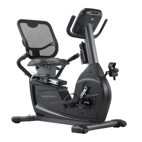
R400g PARTS CONTENTS Rear Stabilizer Front Stabilizer Main Bike Assembly Right Left Seat Pad andlebar Handlebar Console Mast Back Pad Bottle Water Console Computer Cover Holder Bottle Mast Console Cover Mesh Back Pad Left Right Pedal Pedal... -
Page 6: Assembly
ASSEMBLY Step 1 Front & Rear Stabilizer 1. Use a Styrofoam block from the packing material to raise the front of the Bike Assembly then attach the Front Stabilizer (2) using two 3/8" x 2-1/4" Hex Head Bolts (79), as shown in Fig. - Page 7 ASSEMBLY Step 3 Handlebars Pulse Handlebar Wire (42) to the Pulse Coiled Wire (41) on the Seat Frame (5). Store excess Spring Washers (104), and two M8 x 15L Dome Head Allen Bolts (84) as shown in Fig. C1. Insert the Seat Adjustment Handle (11) into the bracket welded to the Seat Frame (5). As M8 x 8L Set Screws (97) and then tighten the Set Screws (97) against the flat side.
- Page 8 ASSEMBLY Step 5 Console Mast & Computer Console Be Careful not to pinch any of the wires while assembling IMPORTANT the Console Mast and Computer. NOTE! Slide the Console Mast Cover (30) onto the Console Mast (6). See Fig. E1 and E2. Hold the Console Mast (6) close to the Bike Assembly and connect both wires;...
- Page 9 BATTERY INSTALLATION ATTENTION! Battery must be connected before using this console. Please open the battery cover and connect the battery plug to activate the console. Failure to do so will result console to malfunction. Must connect this plug in order for the console to operate.
-
Page 10: Adjustments
ADJUSTMENTS The seat can adjust front-to-back to accommodate your leg length. Simply rotate the Seat Adjustment Handle (11) upward to loosen then rotate downward with force to lock the seat into place. The Mesh Back Support (18) can be adjusted for your comfort. -
Page 11: Detailed Parts List
DETAILED PARTS LIST DESCRIPTION QTY. MAIN FRAME FRONT STABILIZER REAR STABILIZER SLIDING SEAT TRACK SEAT FRAME CONSOLE MAST LEFT HANDLEBAR RIGHT HANDLEBAR BACK SUPPORT FRAME SEAT TRACK BACKING PLATE BACK PAD ADJUSTMENT LEVER SEAT ADJUSTMENT HANDLE 12 L LEFT CRANK ARM 12 R RIGHT CRANK ARM ASSIST SHOCK... - Page 12 DETAILED PARTS LIST DESCRIPTION QTY. 33 L LEFT SHROUD (pre-assembled) 33 R RIGHT SHROUD (pre-assembled) BRAKE MOTOR ASSEMBLY 34-1 8 PIN CONSOLE MAST HARNESS 8 PIN CONSOLE MAST HARNESS POWER RECEPTACAL HARNESS 36-1 HARNESS OF CONTROL BOARD AND SELF-POWERED GENERATOR SYSTEM SPEED SENSOR PICKUP CABLE 6 PIN 4 PIN CONSOLE MAST HARNESS PULSE CONNECTHARNESS...
- Page 13 DETAILED PARTS LIST DESCRIPTION QTY. 1/2" X 3-1/2" HEX HEAD BOLT 3/8" X 2-3/4" HEX HEAD BOLT 3/8" X 2-1/4" HEX HEAD BOLT M8 X 85L HEX HEAD BOLT M8 X 20L HEX HEAD THREADED BOLT M8 X 40L DOME HEAD ALLEN BOLT M8 X 20L DOME HEAD ALLEN BOLT M8 X 15L DOME HEAD ALLEN BOLT M8 X 30L FLAT HEAD ALLEN BOLT...
- Page 14 EXPLODED VIEW 1 of 2 104 119...
- Page 15 34-1 EXPLODED VIEW 2 of 2 36-1...
- Page 16 COMPUTER OPERATION Console Operation Instruction Please thoroughly read the console operation instructions before use. It is important that you get familiar with the computer console and understand the functions. Below is the console layout and detailed operation instructions. Layout: Data display windows Alphanumeric display window...
- Page 17 COMPUTER OPERATION Data display windows: · There are 8 data display windows displaying “speed, time, distance, calories, rpm, level watts, and pulse” during exercising. Alphanumeric display window: this display will prompt instruction messages to assist you setting up · the program and during exercising. Keys Go key: Pressing this key during idle mode before you select a program will activate the Quick Start ·...
- Page 18 COMPUTER OPERATION o Age – 35 o Weight – 150lbs or 70kg o Program time – 30 minutes o Target HR & Work HR – 70% max HR (Max HR is calculated as 220-age) · End a program and review summary: When program time is reached, it will end the program and enter summary review mode.
- Page 19 COMPUTER OPERATION Strength program profile: · HR programs: The Heart Rate programs are designed to keep you training at the chosen heart rate level. These programs will only work when there is a valid heart rate signal. For your safety, the program will start with a warm up session to get the heart rate up within 20% of the target before it begins the heart rate training session.
-
Page 20: Computer Operation
Built in Wireless Heart Rate Receiver Note: Chest strap transmitter does not come with this unit; contact BODYCRAFT, or your dealer for purchase. This product is equipped with a built-in receiver for your heart rate monitoring. Any heart rate telemetry strap that transmits at 5 kHz is compatible. - Page 21 COMPUTER OPERATION 2. Adjust the band length so that the fit is snug, but not too tight. 3. Buckle the other end of the chest strap onto the transmitter. 4. Center the transmitter on your chest below the pectoral muscle (breasts). 5.
-
Page 22: Warranty
*This warranty is in lieu of all warranties, expressed or implied, and/or all other obligations or liabilities on our part and we neither assume nor authorize any person to assume for us any other obligation or liability in connection with the sale of your BodyCraft product. Under no...
Need help?
Do you have a question about the R400g and is the answer not in the manual?
Questions and answers