Table of Contents
Advertisement
EVERLAST
POWER MTS 211Si
A Digitally-Controlled, Multi-Process MIG/TIG/Stick Welder
CC
CV
GMAW
SMAW
GTAW
IGBT
DC
Operator's Manual for the PowerMTS 211Si
Safety, Setup and General Use Guide
Rev. 1
0 11220-16
everlastwelders.com
Specifications and Accessories subject to change without notice.
1-877-755-9353
329 Littlefield Ave. South San Francisco, CA 94080 USA
Advertisement
Table of Contents

Summary of Contents for Everlast POWER MTS 211Si
- Page 1 EVERLAST POWER MTS 211Si A Digitally-Controlled, Multi-Process MIG/TIG/Stick Welder GMAW SMAW GTAW IGBT Operator’s Manual for the PowerMTS 211Si Safety, Setup and General Use Guide Rev. 1 0 11220-16 everlastwelders.com Specifications and Accessories subject to change without notice. 1-877-755-9353 329 Littlefield Ave. South San Francisco, CA 94080 USA...
-
Page 2: Table Of Contents
Table of Contents Section……………………………………………….Page Letter to the Customer …………………..………… Everlast Contact Information…………….…………. Safety Precautions…………………………………… Introduction and Specifications…..………………… Overview of Parameters and Specifications……. Technical Parameters……………………………... General Description, Purpose and Features……. Set Up Guide and Component Identification….…... Suggested Settings…….…………………...…….. Connections and Polarity…………………………. -
Page 3: Letter To The Customer
It is also important so that we may track your satisfaction with Everlast products and services. If you are unable to register by web- site, contact Everlast directly through the sales department at the main customer service number in your country. -
Page 4: Everlast Contact Information
Serial number: _____________________________ Model number: _____________________________ Date of Purchase:___________________________ Contact Information Everlast US: Everlast consumer satisfaction email: sales@everlastwelders.com Everlast Website: everlastwelders.com Everlast Technical Support: support@everlastwelders.com Everlast Support Forum: http://www.everlastgenerators.com/forums/index.php Main toll free number: 1-877-755 WELD (9353) 9am—5pm PST M-F 11am-4pm PST Sat. -
Page 5: Safety Precautions
Safety Precautions Everlast is dedicated to providing you with the best possible equipment and service to meet the demands of the welding applications that you have. We want to go beyond delivering a satis- factory product to you. That is the reason we offer technical support to assist you with your needs should an occasion occur. - Page 6 Safety Precautions These safety precautions are for protection of your safety and health. Failure to follow these guidelines may result in serious injury or death. Be careful to read and follow all cautions and warnings. Protect yourself and others from danger and injury. Welding and cutting processes produce high levels of ultraviolet (UV) radiation that can cause se- vere skin burn and damage.
- Page 7 Safety Precautions WARNING! Persons with pacemakers should not weld, cut or be in the welding area until they consult with their physician. Some pacemakers are sensitive to EMF radiation and could severely malfunction while welding or while being in the vicinity of someone welding. Serious injury or death may occur! Welding and plasma cutting processes generate electro-magnetic fields and radiation.
- Page 8 Safety Precautions WARNING! Electrical shock can kill. Make sure all electrical equipment is properly grounded. Do not use frayed, cut or otherwise damaged cables and leads. Do not stand, lean or rest on ground clamp. Do not stand in water or damp areas while welding or cutting. Keep work surface dry. Do not use welder or plasma cutter in the rain or in extremely humid conditions.
-
Page 9: Introduction And Specifications
Section 1 Introduction and Specifications Overview of Parameters and Features* PowerMTS 211Si** MIG/TIG/Stick Amp Range 120V: MIG 30-125A/ TIG 10-125A/ Stick 10-100A 240V: MIG 30-200A/ TIG 10-200A/ Stick 10-175A Volt Adjustment Range MIG 120V: 15.5-20V 240V: 15.5-26V MIG Wire Feed Speed 120V: 60-400 (5-10 m/min) 240V: 60 to 600 IPM (.5-15 m/min) Input Voltage... -
Page 10: Technical Parameters
Section 1 Introduction and Specifications EVERLAST POWERMTS 211Si MODEL: PowerMTS 211Si Serial No. EN/ IEC60974.1 240V; DC: 30-210A; 15.5-24.5V 120V; DC: 30-150A; 15.5-20.5V 100% 100% 210A 160A 130A 125A 100A 24.5V 20.5V 20.2V 240V; DC: 10-200A; 10.4-18.4V 120V; DC: 10-1250A; 10.4-15V... -
Page 11: General Description, Purpose And Features
Additional TIG consumable spool gun which is ideal for this type application. How- kits can be purchased from Everlast which include ever, the main spindle and roll carrier can be adapted stubby consumables or gas lens kits with Tungsten to accommodate 4”... -
Page 12: Suggested Settings
4) If used on a mobile cart, strap or fix the welder to the user may want to consider the Everlast SM200N -MTS gun which is a 200+ Amp gun with a 24 series the cart so that accidental overturn is not likely. - Page 13 Section 1 Introduction and Specifications amount of time (expressed as a percentage) out of 10 minutes the unit can weld without a rest. For MIG, the unit is capable of welding 4 minutes out of every 10 minutes at the maximum output of 200 Amps. For the balance of the 10 minute period, the unit should be allowed to rest and cool while running.
-
Page 14: Setup Guide And Component Identification
WORK WORK CONTROL SPOOL GUN + ** Spool gun is an optional item that may be pur- chased separately from Everlast. STICK NOTE: In TIG mode, the user must choose between pedal opera- tion or torch switch operation. Both cannot be in use at the same time. -
Page 15: General Polarity And Amp Recommendations
Section 2 Setup Guide and Component Identification GENERAL POLARITY RECOMMENDATIONS* Table 1 *Consult the manufacturer of the filler material recommendations concerning polarity . PROCESS TORCH POLARITY WORK POLARITY MIG (GMAW) FLUX CORE (FCAW) STICK (SMAW) TIG (GTAW) GAS SELECTION GUIDE Table 2 PROCESS MIG (GMAW) STEEL... - Page 16 Section 2 Setup Guide and Component Identification TIG (GTAW) OPERATION GUIDE FOR STEEL (ALUMINUM)* *As a general rule, set amperage using 1 amp for every .001” of metal thickness for aluminum. Less is required for DC. METAL THICKNESS WELDING AMPS TUNGSTEN DIA.
-
Page 17: Installing The Wire Spool
Section 2 Setup Guide and component Identification INSTALLING THE WIRE SPOOL To load the spool of wire: Loosen and remove the hand nut (if present) on the spool carrier by turning it counter-clockwise. Align the locating pin with the hole on the wire spool (if present). Slide spool onto the shaft. -
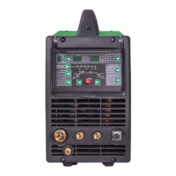
Page 18: Front View Main Panel
Section 2 Setup Guide and Component Identification FRONT VIEW/ MAIN PANEL POWER i-MIG 211Si... -
Page 19: Front Panel Item Description And Explanation
Section 2 Setup Guide and Component Identification Front Panel Description and Explanation: charge. This is part of normal operation and not 1. Protective Cover. The unit features a protective a defect. hinged cover. This cover should be lowered 5. LED Stop Indicator. This indicator will light up whenever welding is actively taking place or anytime a machine fault or an electrical issue is when the welder is stored for an extended peri-... - Page 20 Section 2 Setup Guide and Component Identification cleared from memory. While in synergic mode, since wire speed/amp control is routed through you will notice while cycling between different the gun, but will still be able to fine tune voltage wire types and wire thicknesses, the basic volt on the panel if needed.
- Page 21 Section 2 Setup Guide and Component Identification many MIG/TIG/Stick welders in this class. It is supporting E 6010 use if this rod is frequently more primitive, but does a good job when HF start used. However, most all other rods weld easily is not required or is restricted in HF sensitive envi- in stick mode.
- Page 22 Section 2 Setup Guide and Component Identification 15. Euro Quick Connect for MIG Gun. This style of rods. connection makes the PowerMTS compatible 12. Sequencer. The sequencer controls the arc with many after market MIG torches/guns. cycle and other related parameters to the se- Connect the MIG torch by aligning pins on the lected process’s function.
- Page 23 Section 2 Setup Guide and Component Identification without an adjustable arc force, do have some Flux-core or dual shield, change polarity inside fixed level of inductance, though not all are set at the machine by changing the buss-bar position, the same level. A user can either adjust the induct- unless the wire manufacturer states to use elec- ance to have a familiar feel, or to improve arc be- trode positive.
- Page 24 Section 2 Setup Guide and Component Identification adjustable. For MIG operation, the up and down welders do not provide Pre and Post flow of slope functions are similar in concept, except the shielding gas. This is a reason that many people unit is actually upsloping and downsloping voltage, do not consider MIG for high quality welds, instead of amps.
- Page 25 Section 2 Setup Guide and Component Identification the toes of the weld, or burn though may occur. In Pulse MIG mode, the MIG Volts will not be se- lectable and will default to MIG Pulse Volts when the Voltage is selected. Voltage is not adjustable in TIG or Stick mode.
-
Page 26: Side View
Section 2 Setup Guide and Component Identification SIDE VIEW POWER MTS 211Si... -
Page 27: Side View Item Description And Explanation
Section 2 Setup Guide and Component Identification the wire burns back into tip, sticks fast in the weld Side Description and Explanation: puddle or other resistance is met. This will continue 1. Wire Spool Carrier Assembly. Make note of the wrap the wire around the drive mechanism or will correct assembly order if disassembled. -
Page 28: Rear View Back Panel
Section 2 Setup Guide and Component Identification REAR VIEW/BACK PANEL POWERMTS 211Si 1x120/220V FUSE... -
Page 29: Rear Panel Item Description And Explanation
Everlast does not provide a list of approved gen- 6. Ground Bolt. The unit is equipped with an ad- erators. Manufacturers rate their units as clean... -
Page 30: Basic Theory And Function
The issue with fol- While Everlast uses the term “arc force”, it is known lowing charts, graphs and calculator recommenda- by many different terms. Often it is referred to as in- tions is that most people find them either too hot or ductance, choke or slope. - Page 31 Basic Theory and Function Section 3 BASIC MIG OPERATION current to recover and rise to the established weld- For the best possible experience welding with the ing current to melt the wire after the wire contacts PowerMTS welder, adjust the arc force after the the puddle and the current falls.
- Page 32 Basic Theory and Function Section 3 BASIC MIG OPERATION control is set correctly, it will leave about 1/4”-3/8” be in the vertical position, with no more than 5 de- wire sticking out beyond the contact tip. If a large grees lean in either side to side direction. Holding ball develops on the end of the wire, reduce the the wire too far off from the metal will result in burn back time so that it creates a balance between...
- Page 33 Basic Theory and Function Section 3 BASIC MIG OPERATION portunity for cold lap. Moving too quickly however top of the cooled metal. They are easily brushed off with a stringer can create undercut which will weak- before starting the next pass. They should not be en the weld.
- Page 34 Basic Theory and Function Section 3 BASIC MIG OPERATION Besides a butt joint and lap joint which are often used DOUBLE V-GROOVE V-GROOVE (60-80°) for thinner metal gauges, consider using one of these groove joints for best welding results. When grinding or cutting the bevels, especially with a single V- groove, it may be beneficial to leave a small land with U-GROOVE...
- Page 35 Basic Theory and Function Section 3 BASIC MIG OPERATION Problem: Gun is not being held vertical from side to side. Wire is not being directed to the center of the puddle. This concentrates heat on one side of the joint and results in poor fusion on the neglected side.
- Page 36 Section 2 Setup Guide and component Identification BASIC MIG OPERATION Characteristics: Concave weld, poor filling, possi- ble undercutting resulting in weak weld. Possible Causes: Voltage too high, not enough wire speed, too short of wire stick out, wrong gun angle. Remedy: Decrease voltage, use push motion, in- crease wire speed.
-
Page 37: Mig Work Sheets
Basic Theory and Function Section 3 MIG OPERATION MIG Work Sheet 1 Metal Type_________ Metal Thickness Wire Diameter Wire Speed/Amps Inductance% PGM # NOTES:... - Page 38 Basic Theory and Function Section 3 MIG OPERATION MIG Work Sheet 2 Metal Type_________ Metal Thickness Wire Diameter Wire Speed/Amps Inductance% PGM # NOTES:...
- Page 39 Basic Theory and Function Section 3 MIG OPERATION MIG Work Sheet 3 Metal Type_________ Metal Thickness Wire Diameter Wire Speed/Amps Inductance% PGM # NOTES:...
- Page 40 Basic Theory and Function Section 3 MIG OPERATION MIG Work Sheet 4 Metal Type_________ Metal Thickness Wire Diameter Wire Speed/Amps Inductance% PGM # NOTES:...
- Page 41 Basic Theory and Function Section 3 MIG OPERATION MIG Work Sheet 5 Metal Type_________ Metal Thickness Wire Diameter Wire Speed/Amps Inductance% PGM # NOTES:...
- Page 42 Basic Theory and Function Section 3 MIG OPERATION MIG Work Sheet 6 Metal Type_________ Metal Thickness Wire Diameter Wire Speed/Amps Inductance% PGM # NOTES:...
-
Page 43: Stick Operation
Basic Theory and Function Section 3 STICK OPERATION STARTING METHODS Tapping Method Scratch/Match Method Striking the Arc Make sure the unit is turned on and the startup cycle has finished. Select the Stick icon on the Process Selector. Make sure the electrode holder is in the Positive connector and the work clamp is in the negative connector. Select the Amp level desired. -
Page 44: Special Notes Concerning Operation
Basic Theory and Function Section 3 mended, and it is possible. But when Special Notes Concerning Operation. more CO2 is added, the rust resistance of 1. Shielding Gas Selection for MIG and TIG. stainless goes down due to the added car- While welding aluminum with the Spool bon content. - Page 45 Everlast for your unit. For the best match- foot pedal while providing more accurate up, we recommend the PowerSpool SM control.
- Page 46 Basic Theory and Function Section 3 and downslope of the Volts with the se- quencer. NOTE: For MIG operation, the user must choose between the two. There is no other operation style similar to a foot pedal for MIG. The “T” refers to the number of “travels”...
-
Page 47: Basic Tig Operation
Basic Theory and Function Section 3 Basic TIG Operation Welding. If you are new to TIG welding, it’s General Setup. The process to set up the important that you understand that TIG weld- welder for the basic TIG mode is much less in- ing is much slower than MIG or Stick welding. - Page 48 Basic Theory and Function Section 3 Basic TIG Operation middle finger grasp the rod with the thumb forms. If you need, count as you time your propelling it forward. Other rod manipulation dips until you can do it without thinking. As variations may be used, but the key is to devel- you proceed to dip your rod into the edge of op a comfortable, natural movement that is...
-
Page 49: Tig Arc Starting
Basic Theory and Function Section 3 Note: A TIG lift start should use a nearly seamless motion. Use a light touch and a quick motion for best results. LIFT START OPERATION <1/8” Position the edge of the ceramic cup on the metal. Press and hold the torch switch or press the foot pedal. Wait for the Pre-flow to start. -
Page 50: Tungsten Preparation
Basic Theory and Function Section 3 TUNGSTEN PREPARATION 1. Use a dedicated grinding wheel or contamination may re- sult. Do not breath grinding dust! Wear eye protection and gloves. 2. Grip the Tungsten firmly. 3. Grind the Tungsten perpendic- ular to the wheel face. -
Page 51: Tig Work Sheets
Basic Theory and Function Section 3 TIG OPERATION TIG Work Sheet 1 Metal Type_______ Metal Tungsten Filler Gas Flow Welding Pulse Time-On% PGM # Thickness Size/Type Diameter Rate/Type Amps (If Applicable) NOTES:... - Page 52 Basic Theory and Function Section 3 TIG OPERATION TIG Work Sheet 2 Metal Type_______ Metal Tungsten Filler Gas Flow Welding Pulse Time-On% PGM # Thickness Size/Type Diameter Rate/Type Amps (If Applicable) NOTES:...
- Page 53 Basic Theory and Function Section 3 TIG OPERATION TIG Work Sheet 3 Metal Type_______ Metal Tungsten Filler Gas Flow Welding Pulse Time-On% PGM # Thickness Size/Type Diameter Rate/Type Amps (If Applicable) NOTES:...
-
Page 54: 15 Series Mig Torch
MIG gun provided with Power MTS is commonly known as the 15 Series. The Innotec® listed above is currently the default supplier of the 15 series. Everlast is not the torch manufacturer, but equips the PowerMTS units with some of the most proven torches in history. -
Page 55: Series Tig Torch
Basic Theory and Function Section 3 EXPANDED VIEW OF TIG TORCH 5/8” PARTS FOR 17/26 Series Torch ( STYLE MAY VARY) Long Back Cap with O-Ring Short Back Cap Opt. Torch Head Insulator Collet 1/16 or 3/32 Collet Holder Ceramic Cup #5,6, or 7 Tungsten (customer supplied) Torch Cable Torch Handle... -
Page 56: Troubleshooting Guide
Wire continues feeding but no large diameter wires. Check power plug for problems. arc is present. If easily tripped the Resistor value too low. (Contact Everlast if OC is tripping regularly with normal settings.) Potentiometer damaged. Repair or Replace it. Welding Voltage/Current is uncon- trollable Control board damaged. - Page 57 Solenoid is for higher flow of gas. Listen for audible click of gas sticking. Too short of pre-flow or solenoid. If no click is heard, then contact Everlast post-flow Support. Clean weld properly. Increase pre flow or post flow.
-
Page 58: Error Codes
Troubleshooting Guide Section 4 Error Codes Error Code Meaning Possible Cause Over Voltage/Under Voltage Check Power Source, Correct Wiring. Over Current Operating machine on too small of a conductor. Internal machine fault Over Temperature Duty Cycle exceeded. Blocked cooling. Fans not operating properly. Stuck Switch Gun switch is held too long without at- tempting to strike an arc.
Need help?
Do you have a question about the POWER MTS 211Si and is the answer not in the manual?
Questions and answers