Table of Contents
Advertisement
Quick Links
Advertisement
Table of Contents

Subscribe to Our Youtube Channel
Summary of Contents for Edimax IAP1200
- Page 1 IAP1200 User Manual 05-2021 / v1.3...
-
Page 2: Table Of Contents
I-6. Safety Information ......................... 5 II. Quick Setup ....................5 II-1. Initial Setup ..........................6 II-2. Managed AP Mode: Edimax Pro NMS ................. 11 III. Wall Installation ................... 15 IV. Browser Based Configuration Interface ..........18 IV-1. Information ........................20 IV-1-1. - Page 3 IV-3-1-4. WDS ..........................46 IV-3-1-5. Guest Network ......................48 IV-3-2. 5GHz 11ac 11an ......................... 49 IV-3-2-1. Basic ..........................49 IV-3-2-2. Advanced ........................51 IV-3-2-3. Security ........................53 IV-3-2-4. WDS ..........................55 IV-3-2-5. Guest Network ......................57 IV-3-3. WPS ............................58 IV-3-4.
- Page 4 OVERVIEW Your access point can function in two different modes. The default mode for your access point is AP mode. AP mode is a regular access point for use in your wireless network. Managed AP mode acts as a “slave” AP within the AP array (controlled by the AP Controller “master”).
-
Page 5: Product Information
I. Product Information I-1. Package Contents IAP1200 (US) IAP1200 (EU) Quick Installation Guide Screws x 2... -
Page 6: I-2. System Requirements
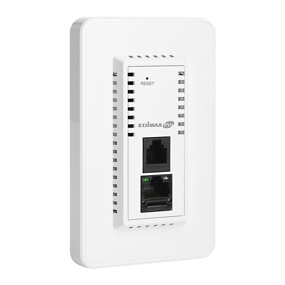
I-2. System Requirements - Ethernet cable - PoE Switch - Computer with web browser for access point configuration I-3. Hardware Overview Reset Button RJ11 Pass-Through LEDs RJ45 Ethernet Port RJ45 Ethernet Port RJ11 Pass-Through... -
Page 7: I-4. Led Status
I-4. LED Status LED Color Status Description The access point is on. Power Green (Right) Flashing The access point is starting up. Green LAN port is connected. Green Flashing LAN activity Orange Flashing Locating access point. (Left) Green & Flashing/ Upgrading firmware. -
Page 8: I-5. Reset
I-5. Reset If you experience problems with your access point, you can reset the device back to its factory settings. This resets all settings back to default. Press and hold the reset button on the access point for at least 10 seconds. -
Page 9: I-6. Safety Information
I-6. Safety Information In order to ensure the safe operation of the device and its users, please read and act in accordance with the following safety instructions. 1. The access point is designed for indoor use only; do not place the access point outdoors. -
Page 10: Ii-1. Initial Setup
NMS. II-1. Initial Setup Connect the IAP1200’s rear Ethernet port to a PoE switch (LAN port) using an Ethernet cable. Use a computer that’s connected to the LAN or connect to the IAP1200’s front Ethernet port using an Ethernet cable. - Page 11 If you changed the access point’s IP address, or if your gateway/router uses a DHCP server, ensure you enter the correct IP address. Refer to your gateway/router’s settings. Login with the default username & password: admin & 1234 You will arrive at the “System Information” screen shown below.
- Page 12 The next steps will help you to configure the following basic settings of the access point: - LAN IP Address - 2.4GHz & 5GHz SSID & Security - Administrator Name & Password - Time & Date It is recommended you configure these settings before using the access point.
- Page 13 require. Then enter a new SSID in the corresponding numbered fields below, before clicking “Apply”. To configure the security of your access point’s 2.4GHz wireless network(s), go to “Wireless Setting” > “2.4GHz 11bgn” > “Security”. Select an “Authentication Method” and enter a “Pre-shared Key” or “Encryption Key”...
- Page 14 Complete the “Administrator Name” and “Administrator Password” fields and click “Apply”. To set the correct time for your access point, go to “Management” > “Date and Time Settings”. Set the correct time and time zone for your access point using the dropdown menus.
-
Page 15: Ii-2. Managed Ap Mode: Edimax Pro Nms
128 access points with the APC 500 AP controller - reducing costs and facilitating efficient remote AP management. Edimax Pro NMS is simple to setup. An overview of the system is shown below: One AP (access point) is designated as the AP Controller (master) and other connected Edimax Pro APs are automatically designated as Managed APs (slaves). - Page 16 IAP1200 as a Managed AP, you can configure the setting manually as below: Ensure all APs including your IAP1200 are connected to an Ethernet or PoE switch which is connected to a gateway/router. You can use your router as a DHCP server or you can later configure your AP Controller as a DHCP server.
- Page 17 Connect a computer to the IAP1200 via PoE switch using an Ethernet cable. Open a web browser and enter the IAP1200’s IP address in the address field. The default IP address is 192.168.2.2...
- Page 18 Enter the username & password to login. The default username & password are admin & 1234. You will arrive at the Edimax Pro NMS Dashboard. Go to “Operation Mode” and select “Managed AP Mode” from the drop down menu. Click “Apply” to save the settings and your AP Controller & Managed APs should be fully functional.
-
Page 19: Iii. Wall Installation
III. Wall Installation The IAP1200 In-Wall access point comes with EU or US wall plates per your region and fits standard sized wall boxes. The Ethernet cable in your wall box must be connected to a PoE switch. Carefully remove the wall plate from the IAP1200 by pulling the plate with a light force to unclip it. - Page 20 Insert the IAP1200 into the wall box, taking care to position the cable properly so it’s not strained. Use the included screws to screw the IAP1200 securely into place and ensure a flush fit with the wall.
- Page 21 Re-attach the wall plate to the IAP1200 by snapping it back into place.
-
Page 22: Iv. Browser Based Configuration Interface
Controller AP to configure your Managed AP(s). The multi-language browser-based configuration interface enables you to configure the access point’s advanced features. The IAP1200 features a range of advanced functions such as MAC filtering, MAC RADIUS authentication, VLAN configurations, 802.11ac Wi-Fi, up to 32 SSIDs and many more. To access the browser based configuration interface: Connect a computer to your access point using an Ethernet cable. - Page 23 Use the menu across the top and down the left side to navigate, and select language with the drop-down menu in the top right corner. Click “Apply” to save changes and reload the access point, or “Cancel” to cancel changes. Please wait a few seconds for the access point to reload after you “Apply”...
-
Page 24: Iv-1. Information
IV-1. Information Screenshots displayed are examples. The information shown on your screen will vary depending on your configuration. IV-1-1. System Information The “System Information” page displays basic system information about the access point. - Page 26 System Model Displays the model number of the access point. Product Name Displays the product name for reference, which consists of “AP” plus the MAC address. Uptime Displays the total time since the device was turned on. Boot From Displays information for the booted hardware, booted from internal memory.
- Page 27 Wireless 2.4GHZ (5GHz) / SSID SSID Displays the SSID name(s) for the specified frequency. Authentication Displays the authentication method for the Method specified SSID. See IV-3. Wireless Settings Encryption Type Displays the encryption type for the specified SSID. See IV-3. Wireless Settings VLAN ID Displays the VLAN ID for the specified SSID.
-
Page 28: Iv-1-2. Wireless Clients
IV-1-2. Wireless Clients The “Wireless Clients” page displays information about all wireless clients connected to the access point on the 2.4GHz or 5GHz frequency. Refresh time Auto Refresh Time Select a time interval for the client table list to automatically refresh. Manual Refresh Click refresh to manually refresh the client table. - Page 29 Signal (%) Displays the wireless signal strength for the specified client. Connected Time Displays the total time the wireless client has been connected to the access point. Idle Time Client idle time is the time for which the client has not transmitted any data packets i.e. is idle.
-
Page 30: Iv-1-3. Wireless Monitor
IV-1-3. Wireless Monitor Wireless Monitor is a tool built into the access point to scan and monitor the surrounding wireless environment. Select a frequency and click “Scan” to display a list of all SSIDs within range along with relevant details for each SSID. Wireless Monitor Site Survey Select which frequency (or both) to scan, and... - Page 31 Signal (%) Displays the current signal strength of the SSID. Type Displays the 802.11 wireless networking standard(s) of the specified SSID. Vendor Displays the vendor of the wireless router/access point for the specified SSID.
-
Page 32: Iv-1-4. Dhcp Client Table
IV-1-4. DHCP Client Table The DHCP client table displays information about DHCP clients when DHCP server is enabled. DHCP Client Table IP Address Displays the IP address of listed DHCP client. MAC Address Displays the MAC address of listed DHCP client. -
Page 33: Iv-1-5. Log
IV-1-5. The system log displays system operation information such as up time and connection processes. This information is useful for network administrators. When the log is full, old entries are overwritten. Use the Search function to quickly locate log entries. Save Click to save the log as a file on your local computer. - Page 34 The following information/events are recorded by the log: Wireless Client Connected & disconnected Key exchange success & fail Authentication Authentication fail or successful. Association Success or fail WPS M1 - M8 messages WPS success Change Settings ...
-
Page 35: Iv-2. Network Settings
IV-2. Network Settings Screenshots displayed are examples. The information shown on your screen will vary depending on your configuration. IV-2-1. LAN-Side IP Address The “LAN-side IP address” page allows you to configure your access point on your Local Area Network (LAN). You can enable the access point to dynamically receive an IP address from your router’s DHCP server or you can specify a static IP address for your access point, as well as configure DNS servers. - Page 36 Default Gateway For DHCP users, select “From DHCP” to get default gateway from your DHCP server or “User-Defined” to enter a gateway manually. For static IP users, the default value is blank. DHCP users can select to get DNS servers’ IP address from DHCP or manually enter a value.
-
Page 37: Iv-2-2. Lan Port
IV-2-2. LAN Port The “LAN Port” page allows you to configure the settings for your access point’s two wired LAN (Ethernet) ports. Wired LAN Port Identifies LAN port. Enable Enable/disable specified LAN port. Speed & Duplex Select a speed & duplex type for specified LAN port, or use the “Auto”... -
Page 38: Iv-2-3. Igmp Snooping
IV-2-3. IGMP Snooping IGMP snooping monitors Internet Group Management Protocol (IGMP) network traffic in order to optimize wireless multicast traffic performance. IGMP Snooping IGMP Snooping Enable or disable IGMP snooping. -
Page 39: Iv-2-4. Vlan
IV-2-4. VLAN The “VLAN” (Virtual Local Area Network) enables you to configure VLAN settings. A VLAN is a local area network which maps workstations virtually instead of physically and allows you to group together or isolate users from each other. VLAN IDs 1 – 4095 are supported. VLAN IDs in the range 1 –... -
Page 40: Iv-3. Wireless Settings
IV-3. Wireless Settings Screenshots displayed are examples. The information shown on your screen will vary depending on your configuration. IV-3-1. 2.4GHz 11bgn The “2.4GHz 11bgn” menu allows you to view and configure information for your access point’s 2.4GHz wireless network across five categories: Basic, Advanced, Security, WDS &... - Page 41 Wireless Enable or disable the access point’s 2.4GHz wireless radio. When disabled, no 2.4GHz SSIDs will be active. Band Select the wireless standard used for the access point. Combinations of 802.11b, 802.11g & 802.11n can be selected. Enable SSID Number Select how many SSIDs to enable for the 2.4GHz frequency from the drop down menu.
- Page 42 When auto channel is disabled, select a wireless channel manually: Channel Select a wireless channel from 1 – 11. Channel Bandwidth Set the channel bandwidth: 20MHz (lower performance but less interference), 40MHz (higher performance but potentially higher interference) or Auto (automatically select based on interference level).
-
Page 43: Iv-3-1-2. Advanced
IV-3-1-2. Advanced These settings are for experienced users only. Please do not change any of the values on this page unless you are already familiar with these functions. Changing these settings can adversely affect the performance of your access point. Contention Slot Select “Short”... - Page 44 802.11g Protection Enable/disable 802.11g protection, which increases reliability but reduces bandwidth (clients will send Request to Send (RTS) to access point, and access point will broadcast Clear to Send (CTS), before a packet is sent from client.) 802.11n Protection Enable/disable 802.11n protection, which increases reliability but reduces bandwidth (clients will send Request to Send (RTS) to access point, and access point will broadcast...
-
Page 45: Iv-3-1-3. Security
IV-3-1-3. Security The access point provides various security options (wireless data encryption). When data is encrypted, information transmitted wirelessly cannot be read by anyone who does not know the correct encryption key. It’s essential to configure wireless security in order to prevent unauthorised access to your network. - Page 46 2.4GHz Wireless Security Settings SSID Selection Select which SSID to configure security settings for. Broadcast SSID Enable or disable SSID broadcast. When enabled, the SSID will be visible to clients as an available Wi-Fi network. When disabled, the SSID will not be visible as an available Wi-Fi network to clients –...
-
Page 47: Iv-3-1-3-1. No Authentication
IV-3-1-3-1. No Authentication Authentication is disabled and no password/key is required to connect to the access point. Disabling wireless authentication is not recommended. When disabled, anybody within range can connect to your device’s SSID. IV-3-1-3-2. WEP WEP (Wired Equivalent Privacy) is a basic encryption type. For a higher level of security consider using WPA encryption. -
Page 48: Iv-3-1-3-5. Wpa-Eap
your selection. Encryption Select “TKIP/AES Mixed Mode” or “AES” encryption type. Key Renewal Specify a frequency for key renewal in Interval minutes. Pre-Shared Key Choose from “Passphrase” (8 – 63 Type alphanumeric characters) or “Hex” (up to 64 characters from 0-9, a-f and A-F). Pre-Shared Key Please enter a security key/password according to the format you selected above. - Page 49 MAC-RADIUS Authentication Restrict wireless clients access based on MAC address via a RADIUS server, or password authentication via a RADIUS server. See IV-3-4.RADIUS to configure RADIUS servers. WPS must be disabled to use MAC-RADIUS authentication. See IV-3-3. for WPS settings. MAC RADIUS Select whether to use MAC address or Password...
-
Page 50: Iv-3-1-4. Wds
IV-3-1-4. WDS Wireless Distribution System (WDS) can bridge/repeat access points together in an extended network. WDS settings can be configured as shown below. When using WDS, configure the IP address of each access point to be in the same subnet and ensure there is only one active DHCP server among connected access points, preferably on the WAN side. - Page 51 2.4GHz WDS Functionality Select “WDS with AP” to use WDS with access point or “WDS Dedicated Mode” to use WDS and also block communication with regular wireless clients. When WDS is used, each access point should be configured with corresponding MAC addresses, wireless channel and wireless encryption method.
-
Page 52: Iv-3-1-5. Guest Network
IV-3-1-5. Guest Network You can setup an additional “Guest” Wi-Fi network so guest users can enjoy Wi-Fi connectivity without accessing your primary networks. Enable a guest network and then configure the settings. Guest Network 2.4GHz SSID Displays the guest network name (SSID). Guest Network Enable or disable the guest network. -
Page 53: Iv-3-2. 5Ghz 11Ac 11An
IV-3-2. 5GHz 11ac 11an The “5GHz 11ac 11an” menu allows you to view and configure information for your access point’s 5GHz wireless network across five categories: Basic, Advanced, Security, WDS & Schedule. IV-3-2-1. Basic The “Basic” screen displays basic settings for your access point’s 5GHz Wi-Fi network (s). - Page 54 802.11n & 802.11ac can be selected. Enable SSID Number Select how many SSIDs to enable for the 5GHz frequency from the drop down menu. A maximum of 16 can be enabled. SSID# Enter the SSID name for the specified SSID (up to 16).
-
Page 55: Iv-3-2-2. Advanced
IV-3-2-2. Advanced These settings are for experienced users only. Please do not change any of the values on this page unless you are already familiar with these functions. Changing these settings can adversely affect the performance of your access point. Guard Interval Set the guard interval. - Page 56 Tx Power Set the power output of the wireless radio. You may not require 100% output power. Setting a lower power output can enhance security since potentially malicious/unknown users in distant areas will not be able to access your signal. Beacon Interval Set the beacon interval of the wireless radio.
-
Page 57: Iv-3-2-3. Security
IV-3-2-3. Security The access point provides various security options (wireless data encryption). When data is encrypted, information transmitted wirelessly cannot be read by anyone who does not know the correct encryption key. It’s essential to configure wireless security in order to prevent unauthorised access to your network. - Page 58 Wireless Client Enable or disable wireless client isolation. Isolation Wireless client isolation prevents clients connected to the access point from communicating with each other and improves security. Typically, this function is useful for corporate environments or public hot spots and can prevent brute force attacks on clients’ usernames and passwords.
-
Page 59: Iv-3-2-4. Wds
IV-3-2-4. WDS Wireless Distribution System (WDS) can bridge/repeat access points together in an extended network. WDS settings can be configured as shown below. When using WDS, configure the IP address of each access point to be in the same subnet and ensure there is only one active DHCP server among connected access points, preferably on the WAN side. - Page 60 5GHz WDS Mode WDS Functionality Select “WDS with AP” to use WDS with access point or “WDS Dedicated Mode” to use WDS and also block communication with regular wireless clients. When WDS is used, each access point should be configured with corresponding MAC addresses, wireless channel and wireless encryption method.
-
Page 61: Iv-3-2-5. Guest Network
IV-3-2-5. Guest Network You can setup an additional “Guest” Wi-Fi network so guest users can enjoy Wi-Fi connectivity without accessing your primary networks. Enable a guest network and then configure the settings. Guest Network 5GHz SSID Displays the guest network name (SSID). Guest Network Enable or disable the guest network. -
Page 62: Iv-3-3. Wps
IV-3-3. WPS Wi-Fi Protected Setup is a simple way to establish connections between WPS compatible devices. WPS can be activated on compatible devices by pushing a WPS button on the device or from within the device’s firmware/configuration interface (known as PBC or “Push Button Configuration”). When WPS is activated in the correct manner and at the correct time for two compatible devices, they will automatically connect. - Page 63 Check/uncheck this box to enable/disable WPS functionality. WPS must be disabled when using MAC-RADIUS authentication (see IV-3-1-3-6 & IV-3-4). Product PIN Displays the WPS PIN code of the device, used for PIN code WPS. You will be required to enter this PIN code into another WPS device for PIN code WPS.
-
Page 64: Iv-3-4. Radius
IV-3-4. RADIUS The RADIUS menu allows you to configure the access point’s external RADIUS server settings. A RADIUS server provides user-based authentication to improve security and offer wireless client control – users can be authenticated before gaining access to a network. The access point can utilize both a primary and secondary (backup) external RADIUS server for each of its wireless frequencies (2.4GHz &... -
Page 65: Iv-3-4-1. Radius Settings
IV-3-4-1. RADIUS Settings Configure the RADIUS server settings for 2.4GHz. Each frequency can use an internal or external RADIUS server. - Page 66 RADIUS Type Select “Internal” to use the access point’s built-in RADIUS server or “external” to use an external RADIUS server. RADIUS Server Enter the RADIUS server host IP address. Authentication Set the UDP port used in the authentication Port protocol of the RADIUS server. Value must be between 1 –...
-
Page 67: Iv-3-4-2. Internal Server
IV-3-4-2. Internal Server The access point features a built-in RADIUS server which can be configured as shown below used when “Internal” is selected for “RADIUS Type” in the “Wireless Settings” “RADIUS” “RADIUS Settings” menu. To use RADIUS servers, go to “Wireless Settings” “Security”... - Page 68 99 characters in length. This should match the “MAC-RADIUS” password used in IV-3-1-3-6 or IV-3-2-3. Session Timeout Set a duration of session timeout in seconds between 0 – 86400. Termination Action Select a termination-action attribute: “Reauthentication” sends a RADIUS request to the access point, “Not-Reathentication”...
-
Page 69: Iv-3-4-3. Radius Accounts
IV-3-4-3. RADIUS Accounts The internal RADIUS server can authenticate up to 256 user accounts. The “RADIUS Accounts” page allows you to configure and manage users. - Page 70 User Name Enter the user names here, separated by commas. Click “Add” to add the user to the user registration list. Reset Clear text from the user name box. Select Check the box to select a user. User Name Displays the user name. Password Displays if specified user name has a password (configured) or not (not configured).
-
Page 71: Iv-3-5. Mac Filter
IV-3-5. MAC Filter Mac filtering is a security feature that can help to prevent unauthorized users from connecting to your access point. This function allows you to define a list of network devices permitted to connect to the access point. Devices are each identified by their unique MAC address. - Page 72 commas, e.g. ‘aa-bb-cc-dd-ee-ff,aa-bb-cc-dd-ee-gg’ Click “Add” to add the MAC address to the MAC address filtering table. Reset Clear all fields. MAC address entries will be listed in the “MAC Address Filtering Table”. Select an entry using the “Select” checkbox. Select Delete selected or all entries from the table.
-
Page 73: Iv-3-6. Wmm
IV-3-6. WMM Wi-Fi Multimedia (WMM) is a Wi-Fi Alliance interoperability certification based on the IEEE 802.11e standard, which provides Quality of Service (QoS) features to IEE 802.11 networks. WMM prioritizes traffic according to four categories: background, best effort, video and voice. Configuring WMM consists of adjusting parameters on queues for different categories of wireless traffic. - Page 74 CWMin Minimum Contention Window (milliseconds): This value is input to the initial random backoff wait time algorithm for retry of a data frame transmission. The backoff wait time will be generated between 0 and this value. If the frame is not sent, the random backoff value is doubled until the value reaches the number defined by CWMax (below).
-
Page 75: Iv-3-7. Schedule
IV-3-7. Schedule The schedule feature allows you to automate the wireless network for specified times. Check/uncheck the box “Enable Wireless Schedule” to enable/disable the wireless scheduling function. The access point’s time and date settings must be set in order to use this function. - Page 76 Remember to Apply your changes and make sure Enable is checked.
-
Page 77: Iv-3-8. Traffic Shaping
IV-3-8. Traffic Shaping The traffic shaping function allows you to regulate network data transfer to ensure or prioritize performance by limiting uplink and downlink speeds according to SSID. Enable Unlimited: 0 Check/uncheck to enable or disable unlimited Mbps transfer speed. Downlink/Uplink The maximum down/uplink capacity in Mbps. -
Page 78: Iv-4. Management
IV-4. Management Screenshots displayed are examples. The information shown on your screen will vary depending on your configuration. IV-4-1. Admin You can change the password used to login to the browser-based configuration interface here. It is advised to do so for security purposes. If you change the administrator password, please make a note of the new password. - Page 79 Account to Manage This Device Administrator Set the access point’s administrator name. Name This is used to log in to the browser based configuration interface and must be between 4-16 alphanumeric characters (case sensitive). Administrator Set the access point’s administrator password. Password This is used to log in to the browser based configuration interface and must be between...
-
Page 80: Iv-4-2. Date And Time
IV-4-2. Date and Time You can configure the time zone settings of your access point here. The date and time of the device can be configured manually or can be synchronized with a time server. Date and Time Settings Local Time Set the access point’s date and time manually using the drop down menus. - Page 81 Saving not. Server Name Enter the host name or IP address of the time server if you wish. Update Interval Specify a frequency (in hours) for the access point to update/synchronize with the NTP server. Time Zone Time Zone Select the time zone of your country/ region. If your country/region is not listed, please select another country/region whose time zone is the same as yours.
-
Page 82: Iv-4-3. Syslog Server
IV-4-3. Syslog Server The system log can be sent to a server. Syslog Server Settings Transfer Logs Check/uncheck the box to enable/disable the use of a syslog server, and enter a host name, domain or IP address for the server, consisting of up to 128 alphanumeric characters. -
Page 83: Iv-4-4. Ping Test
IV-4-4. Ping Test The access point includes a built-in ping test function. Ping is a computer network administration utility used to test whether a particular host is reachable across an IP network and to measure the round-trip time for sent messages. -
Page 84: Iv-5. Advanced
IV-5. Advanced Screenshots displayed are examples. The information shown on your screen will vary depending on your configuration. IV-5-1. LED Settings The access point’s LEDs can be manually enabled or disabled according to your preference. Power/2.4GHz/5GHz/ Select on or off. Diag LED... -
Page 85: Iv-5-2. Update Firmware
Updated firmware versions often offer increased performance and security, as well as bug fixes. You can download the latest firmware from the Edimax website. Do not switch off or disconnect the access point during a firmware upgrade, as this could damage the device. -
Page 86: Iv-5-3. Save/Restore Settings
IV-5-3. Save/Restore Settings The access point’s “Save/Restore Settings” page enables you to save/backup the access point’s current settings as a file to your local computer, and restore the access point to previously saved settings. Save / Restore Settings Using Device Select “Using your PC”... - Page 87 Restore Settings from PC Restore Settings Click the browse button to find a previously saved settings file on your computer, then click “Restore” to replace your current settings. If your settings file is encrypted with a password, check the “Open file with password”...
-
Page 88: Iv-5-4. Factory Default
IV-5-4. Factory Default If the access point malfunctions or is not responding, then it is recommended that you reboot the device (see IV-5.5) or reset the device back to its factory default settings. You can reset the access point back to its default settings using this feature if the location of the access point is not convenient to access the reset button. -
Page 89: Iv-5-5. Reboot
IV-5-5. Reboot If the access point malfunctions or is not responding, then it is recommended that you reboot the device or reset the access point back to its factory default settings (see IV-5-4). You can reboot the access point remotely using this feature. -
Page 90: Iv-6. Operation Mode
IV-6. Operation Mode Screenshots displayed are examples. The information shown on your screen will vary depending on your configuration. The access point can function in two different modes. Set the operation mode of the access point here. The default mode for your access point is AP mode. AP mode is a regular access point for use in your wireless network. -
Page 91: Appendix
V. Appendix V-1. Configuring your IP address The access point uses the default IP address 192.168.2.2. In order to access the browser based configuration interface, you need to modify the IP address of your computer to be in the same IP address subnet e.g. 192.168.2.x (x = 3 – 254). -
Page 92: V-1-1. Windows Xp
V-1-1. Windows XP Click the “Start” button (it should be located in the lower-left corner of your computer), then click “Control Panel”. Double-click the “Network and Internet Connections” icon, click “Network Connections”, and then double-click “Local Area Connection”. The “Local Area Connection Status” window will then appear, click “Properties”. - Page 93 Select “Use the following IP address”, then input the following values: IP address: 192.168.2.10 Subnet Mask: 255.255.255.0 Click ‘OK’ when finished.
-
Page 94: V-1-2. Windows Vista
V-1-2. Windows Vista Click the “Start” button (it should be located in the lower-left corner of your computer), then click “Control Panel”. Click “View Network Status and Tasks”, then click “Manage Network Connections”. Right-click “Local Area Network”, then select “Properties”. The “Local Area Connection Properties” window will then appear, select “Internet Protocol Version 4 (TCP / IPv4)”, and then click “Properties”. - Page 95 Select “Use the following IP address”, then input the following values: IP address: 192.168.2.10 Subnet Mask: 255.255.255.0 Click ‘OK’ when finished.
-
Page 96: V-1-3. Windows 7
V-1-3. Windows 7 Click the “Start” button (it should be located in the lower-left corner of your computer), then click “Control Panel”. Under “Network and Internet” click “View network status and tasks”. - Page 97 Click “Local Area Connection”. Click “Properties”.
- Page 98 Select “Internet Protocol Version 4 (TCP/IPv4) and then click “Properties”.
- Page 99 Select “Use the following IP address”, then input the following values: IP address: 192.168.2.10 Subnet Mask: 255.255.255.0 Click ‘OK’ when finished.
-
Page 100: V-1-4. Windows 8
V-1-4. Windows 8 From the Windows 8 Start screen, you need to switch to desktop mode. Move your curser to the bottom left of the screen and click. In desktop mode, click the File Explorer icon in the bottom left of the screen, as shown below. - Page 101 Right click “Network” and then select “Properties”. In the window that opens, select “Change adapter settings” from the left side.
- Page 102 Choose your connection and right click, then select “Properties”. Select “Internet Protocol Version 4 (TCP/IPv4) and then click “Properties”.
- Page 103 Select “Use the following IP address”, then input the following values: IP address: 192.168.2.10 Subnet Mask: 255.255.255.0 Click ‘OK’ when finished.
-
Page 104: V-1-5. Mac
V-1-5. Mac Have your Macintosh computer operate as usual, and click on “System Preferences” In System Preferences, click on “Network”. Click on “Ethernet” in the left panel. Open the drop-down menu labeled “Configure IPv4” and select “Manually”. - Page 105 Enter the IP address 192.168.2.10 and subnet mask 255.255.255.0. Click on “Apply” to save the changes.
- Page 106 COPYRIGHT Copyright Edimax Technology Co., Ltd. all rights reserved. No part of this publication may be reproduced, transmitted, transcribed, stored in a retrieval system, or translated into any language or computer language, in any form or by any means, electronic, mechanical, magnetic, optical, chemical, manual or otherwise, without the prior written permission from Edimax Technology Co., Ltd.
- Page 107 18.22 dBm A simplified DoC shall be provided as follows: Article 10(9) In-Wall AP Hereby, Edimax Technology Co., Ltd. declares that the radio equipment type is in compliance with Directive 2014/53/EU The full text of the EU declaration of conformity is available at the following internet address: http://www.edimax.com/edimax/global/...
- Page 108 equipment. All guidelines of this and of the computer manufacture must therefore be allowed at all times to ensure the safe use of the equipment. EU Countries Intended for Use The ETSI version of this device is intended for home and office use in Austria, Belgium, Bulgaria, Cyprus, Czech, Denmark, Estonia, Finland, France, Germany, Greece, Hungary, Ireland, Italy, Latvia, Lithuania, Luxembourg, Malta, Netherlands, Poland, Portugal, Romania, Slovakia, Slovenia, Spain, Sweden, Turkey, and United Kingdom.
- Page 109 EU Declaration of Conformity English: This equipment is in compliance with the essential requirements and other relevant provisions of Directive 2014/53/EU, 2014/35/EU. Français: Cet équipement est conforme aux exigences essentielles et autres dispositions de la directive 2014/53/EU, 2014/35/EU. Čeština: Toto zařízení je v souladu se základními požadavky a ostatními příslušnými ustanoveními směrnic 2014/53/EU, 2014/35/EU.
- Page 110 Declaration of Conformity We, Edimax Technology Co., Ltd., declare under our sole responsibility, that the equipment described below complies with the requirements of the European Radio Equipment Directive. Equipment: In-Wall AP Model No.: IAP1200 The following European standards for essential requirements have been followed:...
- Page 111 Notice According to GNU General Public License Version 2 This product includes software that is subject to the GNU General Public License version 2. The program is free software and distributed without any warranty of the author. We offer, valid for at least three years, to give you, for a charge no more than the costs of physically performing source distribution, a complete machine-readable copy of the corresponding source code.
- Page 112 intact all the notices that refer to this License and to the absence of any warranty; and give any other recipients of the Program a copy of this License along with the Program. You may charge a fee for the physical act of transferring a copy, and you may at your option offer warranty protection in exchange for a fee.
- Page 113 Therefore, by modifying or distributing the Program (or any work based on the Program), you indicate your acceptance of this License to do so, and all its terms and conditions for copying, distributing or modifying the Program or works based on it. 6.
Need help?
Do you have a question about the IAP1200 and is the answer not in the manual?
Questions and answers