Table of Contents
Advertisement
Quick Links
Advertisement
Table of Contents

Subscribe to Our Youtube Channel
Summary of Contents for Barco MIVD 1218 MKII
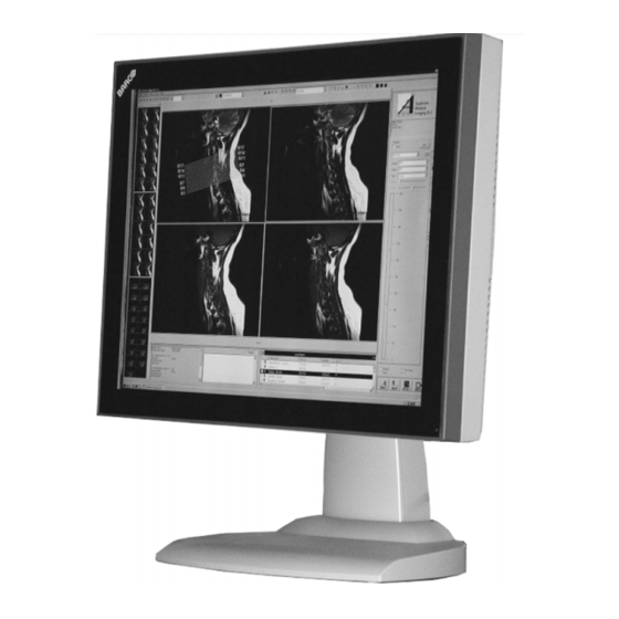
- Page 1 MIVD 1218 MKII Installation & User Manual...
- Page 2 (This page intentionally left blank.) (This page intentionally left blank.)
-
Page 3: Table Of Contents
Table of Contents Table of Contents Preface ....................4 Safety Instructions................ 5 Explanation of symbols..............8 Overview.................... 10 Introduction ................10 Parts, controls and connectors........... 11 Installation ..................14 Display installation..............14 Attaching the display to an arm stand ........17 Operation ................... -
Page 4: Preface
BarcoView software products are the property of BarcoView. They are distributed under copyright by Barco N.V. or BarcoView, LLC., for use only under the specific terms of a software license agreement between Barco N.V. -
Page 5: Safety Instructions
Preface environment. This equipment generates, uses and can radiate radio frequency energy and, if not installed and used in accordance with the instruction manual, may cause harmful interference to radio communications. Operation of this equipment in a residential area is likely to cause harmful interference in which case the user will be required to correct the interference at his own expense. - Page 6 Preface Type of protection (electrical): Class I equipment Degree of safety (flammable anesthetic mixture): Equipment not suitable for use in the presence of a flammable anesthetic mixture with air or with oxygen or nitrous oxide. Power connection • This apparatus must be earthed. •...
- Page 7 Preface Installation Place the display on a flat, solid and stable surface that can support the weight of at least 3 displays. If you use an unstable cart or stand, the display may fall, causing serious injury to a child or adult, and serious damage to the equipment.
-
Page 8: Explanation Of Symbols
Preface Explanation of symbols Symbols on the display and power supply On the display or power supply, you may find the following symbols: Indicates compliance to the essential require- ments of the Directive 93/42/EEC Indicates the display is approved according to the UL regulations Indicates the display is approved according to the c-UL regulations... - Page 9 Preface Indicates the temperature limitations for the display to operate within specs Indicates the display serial no. Consult the operating instructions Indicates this apparatus must not be thrown in the trash but must be recycled, according to the European WEEE (Waste Electrical and Electronic Equipment) directive Symbols used throughout the manual: Warning: Risk of...
-
Page 10: Overview
The power saving system can be switched on or off using the on-screen display. The power saving system works with the standard Windows power saving and with the DPMS function on the Barco BarcoMed display controller (if installed in the PC). -
Page 11: Parts, Controls And Connectors
Overview Option: Portrait Accelerator (PA) The Portrait Accelerator automatically adapts the orientation of the image to the physical orientation of the display panel. The system makes it possible to display a portrait resolution image on a portrait- oriented display without additional software. Option: Tilt &... - Page 12 Overview The LED is green when the display is on (when enabled in the on- screen menus). The LED is orange when the display is in Stand-by power-saving mode. Control wheel The control wheel can be pressed like a push button and rotated like a knob.
- Page 13 Overview Connectors Figure 3 DVI-I video input D-Sub 15 or VGA (analog) video input Analog video input (separate or composite) This is a monochrome video input Video amplitude: 500-950 mV Sync amplitude for composite video: 200-400 mV Composite or Horizontal Sync (CS/HS) input Amplitude: 500 mV to 5V Vertical Sync (VS) input Amplitude: 500 mV to 5V...
-
Page 14: Installation
Installation Installation Precautions • Keep your original packaging. It is designed for this display and is the ideal protection during transport. • Avoid reflections in the flat panel to reduce eye strain. • Place the display on a strong and stable table or desk (desktop version). - Page 15 Installation Video connection The display accepts 4 different video formats: DVI-D (digital), DVI-A (analog), VGA (analog) and BNC (analog, only for monochrome video signals). You can connect one or all of these inputs. If more than 1 input is connected you can switch inputs by using the display’s on-screen display.
- Page 16 Installation Figure 6 Connect the other end of the VGA cable to the analog video output of the signal source. Note: If you connect an analog video signal, you may need to perform some image adjustments to obtain optimum image quality.
-
Page 17: Attaching The Display To An Arm Stand
Installation 2) 3) 4) Figure 7 Note: If you connect an analog video signal, you may need to perform some image adjustments to obtain optimum image quality. Please refer to chapter “Operation”. Cable routing Routing the signal cables • Bind the cables in the connector compartment together with the cable tie inside the connector compartment. - Page 18 Installation To attach the display to an arm stand: Attach the arm stand firmly to the panel using 4 screws M4 x 8 4 screws M4 x 8mm Figure 8...
-
Page 19: Operation
Operation Operation Operating precautions Continuous operation of the display with the same image may result in some image sticking on the LCD panel. Over 10 hours operation with the same image content is not recommended. Switching on DPMS on display and PC and activating a good screen saver may decrease the risk of image sticking (image retention). -
Page 20: About The On-Screen Display (Osd)
Operation About the On-Screen Display (OSD) There are two methods to control the display To control the display you can use: • Quick OSD: To quickly access the most important controls. • Extended OSD: To access all the display controls. The extended OSD can be used in two modes: standard and advanced (see further). - Page 21 Operation The possible Quick OSD menus are:: Brightness Contrast Input selection Luminance Horizontal scaling Scaling Information For more information about these menus, please refer to the chapter about the Extended OSD functions. About the Extended OSD The Extended OSD has a hierarchical tree structure, with several levels. The top level is the “Main Menu”.
- Page 22 Operation MIVD 1218 MAIN MENU Autoset Video Contrast Video Brightness Luminance ADJUSTMENTS Adjustments Input Selection Auto Geometry Settings Phase Preset EXIT Information EXIT Main menu and submenu The content of the OSD depends on the selected video input: A number of functions is not present when you have selected the digital (DVI) video input, because the digital video signal requires less adjustment than the analog video signal.
- Page 23 Operation MIVD 1218 MIVD 1218 MAIN MENU MAIN MENU Autoset Luminance Video Contrast Adjustments Video Brightness Input Selection Auto Luminance Settings Adjustments Information Input Selection Auto EXIT Settings Preset Information EXIT Main menu for analog video Main menu for digital video The extended OSD can be used in standard and advanced mode.
- Page 24 Operation MIVD 1218 MAIN MENU Autoset Video Contrast Video Brightness Luminance ADJUSTMENTS Adjustments Input Selection Auto Geometry Settings Phase Preset EXIT Information EXIT Rotate the control wheel Press the control wheel To exit from a menu, rotate the control wheel to select EXIT. - Press the wheel shortly to return to the previous menu.
-
Page 25: Adjustments For A Digital Video Signal
Operation How to save changes When you have changed something and you wish to exit from the main menu, the display asks if you wish to save the changes. Save Changes? Rotate the control wheel to select Yes (to save the changes) or No (if you do not wish to save the changes). - Page 26 Operation When do you need to use the Autoset function? • The first time you use the display with analog video connected. • After connecting or selecting another analog video source (e.g., changing the PC resolution). • In case you notice the image geometry or positioning is not as desired.
-
Page 27: Standard Osd Functions
Operation Standard OSD functions Main menu Name Description Present in DVI mode Autoset Allows to perform automatic image adjustments Video Contrast Adjust contrast of the image Video Brightness Adjust brightness of the image Luminance Adjust the target luminance to which the display will be stabilized. - Page 28 Operation The Autoset menu is not available in DVI mode. Name Description Full Autoset Perform all Autoset functions (below) one after another Automatic Gain Adjust the video levels (black and white) automatically Automatic Geometry Adjust the image geometry automatically. This function displays the complete active video in the center of the screen.
- Page 29 Operation • Automatic Phase: The image should contain sharp black-white transitions, like a line pattern or characters. • Automatic Gain: The image should contain parts that are completely black (0% video amplitude) and parts that are full white (100% video amplitude). Video Contrast This menu is not available in DVI mode.
- Page 30 Operation Luminance Name Description Luminance Target Manually adjust the luminance The calibrated luminance is indicated as 100% Luminance adjusts the overall luminance (light output) of the display. It does not affect the grayscales of the image on the screen. When Ambient Light Compensation (ALC) is switched on, the (manual) luminance adjustment will not work.
- Page 31 Operation Adjustments: Geometry Name Description Present in DVI mode Automatic This is the same function as in the Geometry Autoset menu. Please refer to the description of the Autoset functions above. After Automatic Geometry, the image is centered inside the active video window.
- Page 32 Operation Adjustments: Phase This menu is not available in DVI mode Name Description Automatic Phase This is the same function as in the Autoset menu Frequency Adjust the video sampling frequency manually. This is necessary when you notice abnor- mal vertical banding, which can be seen best on a dot on/dot off pattern.
- Page 33 Operation Input Selection Name Description Auto Automatically selects the input to which a video signal is connected. If more than one video signal is connected, priority is given to DVI-D. DVI-D Select the DVI-digital input. DVI-A Select the DVI-analog input. Select the DB15 (VGA) input.
- Page 34 Operation This menu is not available in DVI mode. For more information about the Presets, please consult the Glossary section Name Description Find next preset Select another Preset from memory that matches the incoming video and sync sig- nals. The number displayed in the OSD is the number of the actual Preset's memory location.
- Page 35 Operation Information - General Information: Name Description Product The display type Serial No Indicates the display serial number SW Version Displays the current internal software ver- sion Display Lifetime Indicates the total time the display has been operating, including the time in stand-by Backlight Lifetime Indicates the total time the display has...
-
Page 36: Advanced Osd Functions
The functions described in this chapter are intended for trained service staff only! Improper use of these functions may cause the display to not function correctly. Barco cannot be held responsible for the results or damage caused by improper use of these functions. About the Advanced functions The advanced functions are extensions of the standard OSD. - Page 37 Operation Advanced functions in the Adjustments menu Ambient Light Compensation Name Description Min ALC Contains two functions to set the mini- mum point of the ALC control system: Min Ambient Light: Enter the value (in Lux) of the darkest possible ambient light condition you are likely to work in.
- Page 38 Operation Advanced functions in the Settings menu Display Function See the Glossary section for more information about display functions. The display contains a number of factory-defined lookup tables (LUTs) to define the display (transfer) function. Name Description DICOM Select a DICOM display function for most medical viewing applications.
- Page 39 Operation Standard input mode Name Description RGB->RGB The R video signal drives the R sub-pix- els, the G video signal drives the G sub- pixels and the B video signal drives the B sub-pixels. This is the preferred set- ting for color display controllers. R->Y The Red video signal from the imaging board is used as luminance value to...
- Page 40 Operation Advanced functions in the Presets menu Clear user Presets Press the control wheel if you wish to reset all the settings of all programmable (=user) Presets. In the menu that appears next, click on Proceed to reset the settings. Advanced functions in the Information menu Backlight Runtime Backlight Runtime indicates the time the backlight has been on since...
-
Page 41: Locking And Unlocking User Controls
Operation Firmware Firmware is a submenu from General Information, containing the following items: Name Description Boot Code Version The version of the internal boot code Run Code Version The version of the internal run code CPLD Code Version The version of the internal CPLD code FPGA Version The version of the internal FPGA code Preset Table Version... - Page 42 Operation Press the control wheel to disable the setting. This is indicated by a cross in the menu. Exit the menus and save the changes. To enable user controls again: Remove power from the display so that the display is completely off.
-
Page 43: Cleaning
Cleaning Cleaning Precautions • Take care not to damage or scratch the glass or LCD panel. • Do not apply pressure on the glass or LCD panel. • Do not apply or spray liquid directly to the glass, panel or cabinet as excess liquid may cause damage to internal electronics. -
Page 44: Cabinet
Cleaning Cabinet Proceed as follows: • Clean the cabinet using a soft cotton cloth, lightly moistened with a recognized cleaning product for medical equipment. • Repeat with water only. • Wipe dry with a dry cloth. • The cabinet has been tested for resistance to the following products: Cidex, Betadine, Alcohol (Isopropyl and Ethyl), Ammonia-based cleaners (Windex) and Aquasonic Gel. -
Page 45: Troubleshooting
Troubleshooting Troubleshooting General tips • If one display from a multi-head system exhibits problems, try to eliminate the problem by switching video cables or power supplies. In that way you can find out if the problem resides in the display or not. Problems and solutions Problem description Possible tests or solutions... - Page 46 Troubleshooting Problem description Possible tests or solutions The image is non-pro- • Select another resolution in the portionally spread out Windows “Display Properties” control over the screen panel • Switch the “Scaling” function (Geometry menu) in the display OSD to “None” or “Best Fit” The previous image •...
-
Page 47: Technical Information
Technical Information Technical Information Technical specifications MIVD 1218 MKII: Item Specification Picture panel 18.1-inch diagonal viewable screen TFT (thin film transistor) active matrix, gray- scale liquid crystal display Resolution Native: 1280 x 1024 Display area (H x V) 359 x 287.2 (mm) Viewing angle Vertical: 170º... - Page 48 Technical Information Item Specification Power consumption 64 watts (max., at 90 VAC, maximum backlight) Dimensions 432 x 362.2 x 107 mm (W x H x D) Net weight 9.1 kg Operating Temperature 0°C to 40°C, 15°C to 35°C within specs Storage Temperature -20°C to 60°C Humidity...
-
Page 49: Connector Pin Assignments
Technical Information Connector pin assignments DVI connector: C1 C2 Figure 10: DVI-I connector pin layout Pin no. Signal Pin no. Signal TMDS DATA 2- HOT PLUG DETECT TMDS DATA 2+ TMDS DATA 0- TMDS DATA 0+ DDC CLOCK DDC DATA Analog VS TMDS CLOCK- TMDS DATA 1-... -
Page 50: Glossary
Technical Information D-Sub 15 connector: Figure 11: D-Sub 15 pin layout Pin no. Signal Pin no. Signal Red in DDC 5V IN Green in VGA PRES Blue in DDC SDA HS IN VS IN DDC SCL Glossary Calibration Each display is calibrated in the factory before it is sent to the customer. After this calibration, black and white luminance are set to the ideal level. - Page 51 Technical Information Display Function A Display Function describes how a display device converts the video signals at the inputs into light. In the context of a medical viewing station, a display device is the combination of display controller (graphics board) and display. The display function is a graph that shows how the light from the display panel evolves from minimum to maximum luminance while the data levels at the input of the display controller go from 0 to maximum.
-
Page 52: Warranty Statement
Warranty Statement Warranty Statement ARTICLE 1: SERVICES BarcoView warrants that the equipment will be free of defects in workmanship or material for the warranty period. Notwithstanding the provisions of clause 2, repair and replacement of defects in material and/or workmanship under this warranty shall be accomplished in our works in the following manner: 1.1 The Customer, upon the occurrence of any equipment failure, shall contact BarcoView Customer Support Center (or an authorized service... - Page 53 Warranty Statement ARTICLE 2: ITEMS EXCLUDED FROM WARRANTY The warranty described herein shall not include the following: 2.1 Any hardware or software item procured from a source other than BarcoView or their official agent or distributor and integrated by Customer or a third party into BarcoView supplied equipment. 2.2 Any host configuration not explicitly supported by BarcoView.
- Page 54 Warranty Statement agents, employees, or representatives, shall be borne by the Customer at its additional cost and expense. 3.3 The customer is responsible for installing the BarcoView equipment in an environment for which it was intended. If there is an indication that the equipment was used - even temporary - outside its specifications, BarcoView is entitled not to perform warranty repairs and terminate the warranty agreement.
- Page 55 Warranty Statement this agreement is impeded by reason of force majeure. For the purposes of this clause the expression “force majeure” means, but shall not be limited to, industrial dispute, fire, mobilization, requisition, embargo, currency transfer prohibitions, insurrection, lack of means of transport, restrictions of the use of energy, and generally any circumstances which are beyond the control of the parties and hinder performance by one party of his obligations.
- Page 56 K5904081-01 October 2006 www.barco.com...
Need help?
Do you have a question about the MIVD 1218 MKII and is the answer not in the manual?
Questions and answers