Table of Contents
Advertisement
Advertisement
Table of Contents

Summary of Contents for TEAMWELDER MMA 300 CEL
- Page 1 Operating instructions Welding machine MMA 300 CEL 299-010300-TWD01 21.09.2015...
- Page 2 +49 2623 9276400. A list of authorised sales partners can be found at www.teamwelder.com. Liability in conjunction with the operation of this system is explicitly limited to the functioning of the system.
-
Page 3: Table Of Contents
Contents Notes on the use of these operating instructions Contents 1 Contents ..............................3 2 Safety instructions ..........................5 Notes on the use of these operating instructions ................5 Explanation of icons ........................6 General ............................7 Transport and installation ......................11 2.4.1 Ambient conditions ....................... - Page 4 Meeting the requirements of RoHS ....................39 7 Rectifying faults ............................ 40 Error messages (power source) ....................40 Resetting welding parameters to the factory settings ..............41 8 Technical data ............................42 MMA 300 CEL ..........................42 9 Accessories ............................43 Internet ............................43 299-010300-TWD01 21.09.2015...
-
Page 5: Safety Instructions
Safety instructions Notes on the use of these operating instructions Safety instructions Notes on the use of these operating instructions DANGER Working or operating procedures which must be closely observed to prevent imminent serious and even fatal injuries. • Safety notes include the "DANGER" keyword in the heading with a general warning symbol. •... -
Page 6: Explanation Of Icons
Safety instructions Explanation of icons Explanation of icons Symbol Description Special technical points which users must observe. Correct Wrong Press Do not press Press and keep pressed Turn Switch Switch off machine Switch on machine enter the menu ENTER Navigating in the menu NAVIGATION Exit the menu EXIT... -
Page 7: General
Safety instructions General General DANGER Electromagnetic fields! The power source may cause electrical or electromagnetic fields to be produced which could affect the correct functioning of electronic equipment such as IT or CNC devices, telecommunication lines, power cables, signal lines and pacemakers. •... - Page 8 Safety instructions General WARNING Smoke and gases! Smoke and gases can lead to breathing difficulties and poisoning. In addition, solvent vapour (chlorinated hydrocarbon) may be converted into poisonous phosgene due to the ultraviolet radiation of the arc! • Ensure that there is sufficient fresh air! •...
- Page 9 Safety instructions General CAUTION Obligations of the operator! The respective national directives and laws must be observed for operation of the machine! • National implementation of the framework directive (89/391/EWG), as well as the associated individual directives. • In particular, directive (89/655/EWG), on the minimum regulations for safety and health protection when staff members use equipment during work.
- Page 10 Safety instructions General CAUTION EMC Machine Classification In accordance with IEC 60974-10, welding machines are grouped in two electromagnetic compatibility classes - See 8 Technical data chapter: Class A machines are not intended for use in residential areas where the power supply comes from the low-voltage public mains network.
-
Page 11: Transport And Installation
Safety instructions Transport and installation Transport and installation WARNING Incorrect handling of shielding gas cylinders! Incorrect handling of shielding gas cylinders can result in serious and even fatal injury. • Observe the instructions from the gas manufacturer and in any relevant regulations concerning the use of compressed air! •... -
Page 12: Ambient Conditions
Safety instructions Transport and installation 2.4.1 Ambient conditions CAUTION Installation site! The machine must not be operated in the open air and must only be set up and operated on a suitable, stable and level base! • The operator must ensure that the ground is non-slip and level, and provide sufficient lighting for the place of work. -
Page 13: Intended Use
Intended use Applications Intended use WARNING Hazards due to improper usage! Hazards may arise for persons, animals and material objects if the equipment is not used correctly. No liability is accepted for any damages arising from improper usage! • The equipment must only be used in line with proper usage and by trained or expert staff! •... -
Page 14: Documents Which Also Apply
In case of unauthorised changes, improper repairs, non-compliance with specified deadlines for "Arc Welding Equipment – Inspection and Testing during Operation", and/or prohibited modifications which have not been explicitly authorised by TEAMWELDER, this declaration shall be voided. An original document of the specific declaration of conformity is included with every product. -
Page 15: Machine Description - Quick Overview
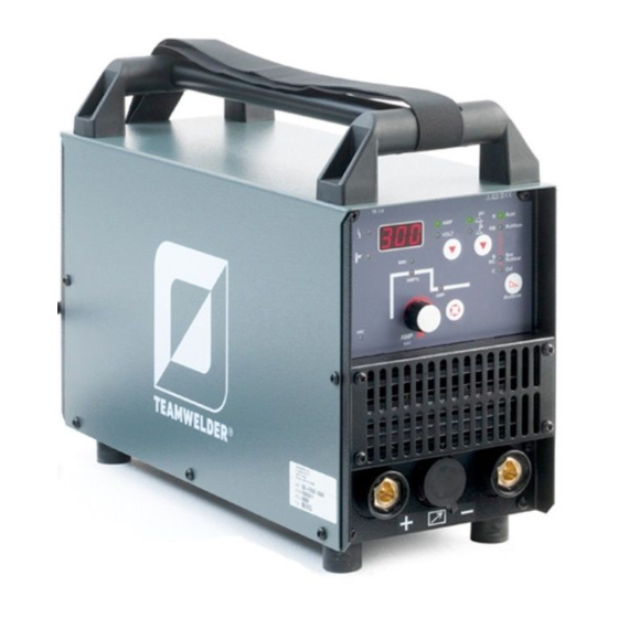
Machine description – quick overview Front view Machine description – quick overview Front view Figure 4-1 Item Symbol Description Carrying handle Transport bar Machine control- See 4.3 Machine control – Operating elements chapter Cooling air inlet Connection socket, 19-pole Remote control connection Connection socket, "+"... -
Page 16: Rear View
Machine description – quick overview Rear view Rear view Figure 4-2 Item Symbol Description Main switch, machine on/off Cooling air outlet Mains connection cable 299-010300-TWD01 21.09.2015... -
Page 17: Machine Control - Operating Elements
Machine description – quick overview Machine control – Operating elements Machine control – Operating elements Figure 4-3 Item Symbol Description Collective interference signal light For error messages, - See 7 Rectifying faults chapter Excess temperature signal light In case of excess temperature, temperature monitors de-activate the power unit, and the excess temperature control lamp comes on. - Page 18 Machine description – quick overview Machine control – Operating elements Item Symbol Description Hotstart current signal light AMP% 50 % to 200 % of the main current Hotstart time signal light (0.1 s to 20 s) Main current signal light 299-010300-TWD01 21.09.2015...
-
Page 19: Design And Function
Design and function General Design and function General WARNING Risk of injury from electric shock! Contact with live parts, e.g. welding current sockets, is potentially fatal! • Follow safety instructions on the opening pages of the operating instructions. • Commissioning may only be carried out by persons who have the relevant expertise of working with arc welding machines! •... -
Page 20: Transport And Installation
Design and function Transport and installation Transport and installation WARNING Risk of accident due to improper transport of machines that may not be lifted! Do not lift or suspend the machine! The machine can fall down and cause injuries! The handles and brackets are suitable for transport by hand only! •... -
Page 21: Machine Cooling
Design and function Machine cooling Machine cooling To obtain an optimal duty cycle from the power components, the following precautions should be observed: • Ensure that the working area is adequately ventilated. • Do not obstruct the air inlets and outlets of the machine. •... -
Page 22: Mains Connection
Design and function Mains connection Mains connection DANGER Hazard caused by improper mains connection! An improper mains connection can cause injuries or damage property! • Only use machine with a plug socket that has a correctly fitted protective conductor. • If a mains plug must be fitted, this may only be carried out by an electrician in accordance with the relevant national provisions or regulations! •... -
Page 23: Notes On The Installation Of Welding Current Leads
Design and function Notes on the installation of welding current leads Notes on the installation of welding current leads Incorrectly installed welding current leads can cause faults in the arc (flickering). Lay the workpiece lead and hose package of power sources without HF igniter (MIG/MAG) for as long and as close as possible in parallel. - Page 24 Design and function Notes on the installation of welding current leads Use an individual welding lead to the workpiece for each welding machine! Figure 5-4 Fully unroll welding current leads, torch hose packages and intermediate hose packages. Avoid loops! Always keep leads as short as possible! Lay any excess cable lengths in meanders.
-
Page 25: Mma Welding
Design and function MMA welding MMA welding CAUTION Risk of being crushed or burnt. When replacing spent or new stick electrodes • Switch off machine at the main switch • Wear appropriate safety gloves • Use insulated tongs to remove spent stick electrodes or to move welded workpieces and •... -
Page 26: Selecting Mma Welding
Design and function MMA welding 5.7.2 Selecting MMA welding Operating Action Result element Select MMA welding process signal light lights up in green Set welding current 5.7.2.1 Arcforce (welding characteristics) During the welding process, arcforce prevents the electrode sticking in the weld pool with increases in current. -
Page 27: Hotstart Current And Hotstart Time
Design and function MMA welding 5.7.3 Hotstart current and Hotstart time The hotstart device uses an increased ignition current to improve arc ignition. The parameters for the hotstart current and time can be adjusted individually. When the stick electrode has been struck, the arc ignites at the adjusted hotstart current AMP% (factory setting: 120 % of main current) and welds at this current until the hotstart time in seconds has elapsed (factory setting: 1 second). -
Page 28: Antistick
Design and function MMA welding 5.7.4 Antistick Anti-stick prevents the electrode from annealing. If the electrode sticks in spite of the Arcforce device, the machine automatically switches over to the minimum current within about 1 second to prevent the electrode from overheating. Check the welding current setting and correct according to the welding task! Figure 5-9 5.7.5... -
Page 29: Tig Welding
Design and function TIG welding TIG welding 5.8.1 Shielding gas supply (shielding gas cylinder for welding machine) WARNING Incorrect handling of shielding gas cylinders! Incorrect handling of shielding gas cylinders can result in serious and even fatal injury. • Observe the instructions from the gas manufacturer and in any relevant regulations concerning the use of compressed air! •... -
Page 30: Connecting The Shielding Gas Supply
Design and function TIG welding 5.8.1.1 Connecting the shielding gas supply • Secure the shielding gas cylinder using a securing chain. Figure 5-11 Item Symbol Description Pressure regulator Shielding gas cylinder Output side of the pressure regulator Cylinder valve • Tighten the pressure regulator screw connection on the gas bottle valve to be gas-tight. -
Page 31: Connecting A Tig Welding Torch With Rotating Gas Valve
Design and function TIG welding 5.8.2 Connecting a TIG welding torch with rotating gas valve Figure 5-12 Item Symbol Description Workpiece Connection socket for "+" welding current Workpiece lead connection Output side of the pressure regulator Welding torch Connection socket, "-" welding current Welding current lead connection for TIG welding torch •... -
Page 32: Setting The Shielding Gas Quantity
Design and function TIG welding 5.8.2.1 Setting the shielding gas quantity CAUTION Electric shocks! When setting the shielding gas quantity, high voltage ignition pulses or open circuit voltage are applied at the welding torch; these can lead to electric shocks and burning on contact. -
Page 33: Tig Welding Selection
Design and function TIG welding 5.8.3 TIG welding selection Control element Action Result TIG welding signal light lights up Main current setting 5.8.4 TIG arc ignition 5.8.4.1 Liftarc ignition Figure 5-13 The arc is ignited on contact with the workpiece: a) Carefully place the torch gas nozzle and tungsten electrode tip onto the workpiece (liftarc current flowing, regardless of the main current set). -
Page 34: Advanced Settings
Design and function Advanced settings Advanced settings To enable the greatest possible breadth of applications, the following parameters can be adjusted or optimised for the welding task. 5.9.1 Arc length restriction (USP) ENTER EXIT Figure 5-14 Display Setting/selection Arc length restriction Function switched on (TIG, factory setting) Function switched off (MMA, factory setting) 299-010300-TWD01... -
Page 35: Activating The Welding Current Actual Value Display
Design and function Advanced settings 5.9.2 Activating the welding current actual value display The welding current can be displayed as a setpoint value or an actual value on the welding data display. The factory setting is that the welding current is displayed as a setpoint value (parameter "rcd" = off). After switching over to the actual value display (parameter "rcd"... -
Page 36: Remote Control
Design and function Remote control 5.10 Remote control Insert the remote control control cable into the 19-pole connection socket for remote control connection and lock. 5.10.1 Manual remote control TW-RT1 19POL Functions • Infinitely adjustable welding current (0% to 100%) depending on the preselected main current on the welding machine. -
Page 37: Dirt Filter
Design and function Dirt filter 5.12 Dirt filter The dirt filter can be used in places with unusually high levels of dirt and dust in the ambient air. The filter reduces the duty cycle of the welding machine via the reduced flow of cooling air. The filter must be disassembled and cleaned regularly depending on the level of dirt (blow out with compressed air). -
Page 38: Maintenance, Care And Disposal
Maintenance, care and disposal General Maintenance, care and disposal DANGER Do not carry out any unauthorised repairs or modifications! To avoid injury and equipment damage, the unit must only be repaired or modified by specialist, skilled persons! The warranty becomes null and void in the event of unauthorised interference. •... -
Page 39: Annual Test (Inspection And Testing During Operation)
07416/08-ECZ, and EKO-KOM with the Reg. No. F00034148. Meeting the requirements of RoHS We, TEAMWELDER Germany GmbH, hereby confirm that all products which we supply to you that are subject to the RoHS Directive comply with the requirements of the RoHS (Directive 2011/65/EU). -
Page 40: Rectifying Faults
Rectifying faults Error messages (power source) Rectifying faults All products are subject to rigorous production checks and final checks. If, despite this, something fails to work at any time, please check the product using the following flowchart. If none of the fault rectification procedures described leads to the correct functioning of the product, please inform your authorised dealer. -
Page 41: Resetting Welding Parameters To The Factory Settings
Rectifying faults Resetting welding parameters to the factory settings Resetting welding parameters to the factory settings All customised welding parameters that are stored will be replaced by the factory settings. RESET A M P VOLT Figure 7-1 Display Setting/selection Calibration The machine will be calibrated for approx 2 seconds each time it is switched on. -
Page 42: Technical Data
Technical data MMA 300 CEL Technical data Performance specifications and guarantee only in connection with original spare and replacement parts! MMA 300 CEL Current setting range 10 A–300 A 5 A–300 A Voltage setting range 20.4 V–32.0 V 10.4 V–22.0 V Duty cycle at 25°C... -
Page 43: Accessories
Accessories Internet Accessories Internet For the accessories available for your product go to www.teamwelder.com. Figure 9-1 299-010300-TWD01 21.09.2015...
Need help?
Do you have a question about the MMA 300 CEL and is the answer not in the manual?
Questions and answers