
Summary of Contents for Ventrac 4200 VXD
- Page 1 OWNER/OPERATOR’S MANUAL TRACTOR 4200 VXD Serial # 1001-2928 REVISED 04-18-07 2ND EDITION Venture Products Inc. Orrville, OH 09.10027...
- Page 2 TO THE OWNER Congratulations on the purchase of a new VENTRAC 4200 VXD! The purpose of this manual is to assist you in its safe and effective operation and maintenance. With proper usage and care, the Tractor will provide many years of service. Please read and understand this manual entirely before using the Tractor.
-
Page 3: Table Of Contents
TABLE OF CONTENTS INTRODUCTION SECTION A Description ........A-1 Specifications . - Page 4 TABLE OF CONTENTS ELECTRICAL DIAGRAMS SECTION E Electrical Components ....... E-1 Kawasaki 27 HP .
-
Page 5: Description
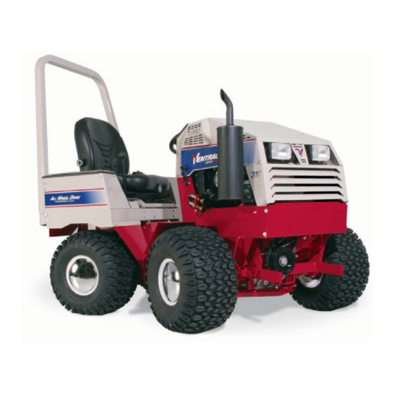
INTRODUCTION Product Description Ventrac 4200 VXD • The Ventrac Series 4200 VXD is a unique all wheel drive tractor that spreads its weight to four equal-sized flotation tires for excellent power, stability, traction, braking and maneuvering. • Performance is enhanced by a sturdy articulated chassis frame which oscillates to conform to ground contour and turns with ease via a hydraulic power steering system. - Page 6 INTRODUCTION Ventrac 4200 VXD Specifications ENGINES: (26.5 TO 31 hp Range) Engine Displacement Kawasaki: ..746 (cc) Gasoline, Model FD750D, 27 hp, 2 Cylinder, Liquid-Cooled Vanguard: . . . 953 (cc) Turbo Diesel, Model DM950DT, 31 hp, 3 Cylinder, Liquid-Cooled Vanguard: .
- Page 7 SAFETY ATTENTION This symbol identifies potential health and safety hazards. It marks safety precautions. Your safety and the safety of The engine exhaust from this product others is involved. contains chemicals known to the State of California to cause cancer, birth defects or other reproductive harm.
-
Page 8: General Safety
SAFETY General Safety Procedures for Ventrac Tractors, Attachments, & Accessories Read and understand the operator’s manual before operating this equipment. Observe and follow all safety decals. DO NOT let children or any untrained person operate the tractor or attachment. Make sure that all operators of this equipment are thoroughly trained in using it safely. - Page 9 SAFETY Ventrac 4200 VXD Safety Procedures Before making any repairs or adjustments, lower attachment to the ground, set parking brake, shut the engine off, and remove the key. Read and understand the operator’s manual before operating this equipment. Before Operating •...
- Page 10 SAFETY SAFETY Slopes • Use low range when on hills and slopes. • Whenever possible, drive up and down a hill….dual wheels are recommended for mowing across slopes. Be careful when you change direction on a slope. Drive slowly. • Make allowances in speed selection for hills, slopes, and rough terrain. If the operator becomes uncomfortable or unsure of the unit’s stability, the operator should slow down or cease operation.
-
Page 11: Front Controls
VENTRAC 4200! The first sight of the VENTRAC 4200 VXD reveals its low profile, four (4) identical drive tires and the articulated frame. Less obvious is the easy-to-use... -
Page 12: High-Low Range
OPERATION The dash shows IMPORTANT operational and safety instructions. A manual choke pull is located Choke Location in the right lower corner for gasoline engine models. Just below the dash on the right side is a three- (3) position Control Selector (Figure 4). 1. -
Page 13: Rear Controls
STOPPING! This shift-on-the-go feature with engine power and brake power to all four tires makes the VENTRAC 4200 VXD an amazing performer in many situations. Yet extreme caution is important to avoid unexpected and difficult situations that could cause serious injury or damage to operator or equipment. -
Page 14: Fenders
(See 3-point hitch section). The VENTRAC 4200 operator’s manual is stored in a holder inside the storage box (Figure 8). It should be kept in a plastic cover for protection and always be readily available to any and all operators. - Page 15 OPERATION SEAT The VENTRAC 4200 VXD has an adjustable seat — fore and aft. Each operator should adjust the seat for the greatest control and comfort in relation to the steering wheel as well as the directional control lever (Figure 11). The seat can also be...
- Page 16 Figure 16 COUNTER WEIGHTS Four 42 pound counter weights are standard equipment on the VENTRAC 4200 VXD. Three 42 pound weights are standard on 3-point hitch models. The weights are mounted close-in as shown in (Figure 17) with retainer pin and clip.
-
Page 17: Pto Belt Tension Lever
OPERATION RIGHT SIDE CONTROLS A - PTO Tension Lever Engaged At the right side of the operator and below the dash, is the PTO belt tension lever, the front hitch lock, and one weight transfer adjustment chain. C - Front PTO BELT TENSION LEVER Hitch Lock Closed... -
Page 18: Front Hitch & Pto
OPERATION WEIGHT TRANSFER The Ventrac integrated "weight transfer system" is designed to transfer some of the front attachment weight onto the tractor. Advantages of this system are: increased traction to the drive wheels, increased lifting capacity and it allows the attachment to float over the surface contours with less weight in contact with the ground. -
Page 19: Pto Engagement
OPERATION AUXILIARY HYDRAULIC HOSES Quick Couplers For attachments that require the front auxiliary hydraulics, install the hoses up through the hose retainer rod and onto the quick couplers on the tractor (Figure 21B). This will keep the hoses Hose Retainer from contacting the tire. -
Page 20: Starting Procedure
OPERATION STARTING PROCEDURE 1. Check engine oil, water, and fuel levels. 2. Read “CAUTION” and instructions on dash. Choke 3. Operator should be sitting on the seat. 4. Fasten seat belt. Park Position 5. Make sure the tractor is in park. (Figure 24) Figure 24 6. -
Page 21: Attaching Attachments
OPERATION ATTACHING ATTACHMENTS Most front mounted Ventrac attachments can be positioned so that it is convenient to drive into the hitch arms with nearly correct alignment (Figure 26 & 27). Slight adjustment may be required to complete the hitch engagement. -
Page 22: Dual Wheel Mounting (Kta Style)
Dual wheels can be used on any or all four wheels. Keeping the center draw bolt tight, the inflation pressure of the outside mounted tire to a max of 4 psi, and operating the Ventrac gently are all important for successful, safe, and continuous performance of the dual wheels. - Page 23 OPERATION Dual Mounting Instructions (Cont.) To install wheel assembly: Raise tractor up approximately 2” by driving on planks or using a jack. Insert threaded end of dual assembly into the inner wheel mount, turn wheel clockwise until the wheel is hand tight. Using a 1” socket, torque draw bolt to 120 ft. Lbs. To remove wheel assembly: Loosen draw bolt (See C-13, Ref 10) approximately 5 turns and hit the end of the draw bolt sharply with a medium size hammer.
-
Page 24: Operating On Slopes
OPERATING ON SLOPES Operation on slopes decreases tractor stability and increases the possibility for unexpected difficulties. Only experienced VENTRAC 4200 VXD operators should operate the tractor on slopes and extra caution should be used that includes: (See drawings at right.) 1. - Page 25 1/2” hydraulic hoses connecting them together require special repair procedures and should only be performed by an authorized Ventrac dealer or service technician. Failure to follow these repair & replacement procedures may cause severe damage and may void all warranty to the hydrostatic...
-
Page 26: Engine Oil
SERVICE & MAINTENANCE Before making any repairs or adjustments, lower attachment to the ground, set parking brake, shut the engine off, and remove the key. See engine manual for oil specifications Each day’s operation of the tractor should begin Vanguard Kawasaki with an oil, water, and fuel check. -
Page 27: Air Intake Filter
This is important for proper performance and life of the hydrostatic system. NOTE: Non-compliance to this specification may void the VENTRAC 4200 VXD warranty. Oil level decal Figure 37 Note: Generally the hydrostatic oil level... -
Page 28: Rear Transaxle
SERVICE & MAINTENANCE REAR TRANSAXLE The rear transaxle oil is captive and remains constant unless there is a leak. For convenience, the same oil is recommended that is used in the front transaxle. Oil can be added through the plug from the rear (Figure 38). -
Page 29: Hydrostatic Oil Filter
A shallow pan or towel can be helpful in containing the oil spill. FUEL LINE FILTER (S) IN-LINE FUEL FILTER All VENTRAC 4200 VXD’s have an in-line fuel filter (Figure 42) located inside the foot platform cover (near engine on Kawasaki models). Pressure Filter Always use clean, fresh fuel. -
Page 30: Diesel Fuel/Water Separator
SERVICE & MAINTENANCE DIESEL FUEL/WATER SEPARATOR Diesel models have a filter/water separator located on the left side of the tractor (Figure 43). Water and sediment can be observed through the glass. Drain water through the small black valve. Remove sediments through the white plug opening. -
Page 31: Brake Adjustment
SERVICE & MAINTENANCE BRAKE ADJUSTMENT A 6” diameter brake band is activated by the Brake 3-position control selector. The brake holds only Adjustment when the lever is in the down position. If brake is not holding sufficiently, tighten the 1/4” nut on the brake linkage, located on the right side, just below the dash (Figure 46). -
Page 32: Neutral Adjustment
2) neutral can easily be determined when tire rotation stops. NOTE: The neutral adjustment procedure is recommended with the engine running around 2000 RPMs. NOTE: If in doubt about this procedure or your efforts fail to remedy the problem, contact your VENTRAC dealer. -
Page 33: Platform Cover
SERVICE & MAINTENANCE PLATFORM COVER (Figure 51) To Remove: 1. Remove bolt at the front of the cover. 2. Pull the cover forward enough to disengage the 2 tabs at the lower rear end of the cover. 3. Lift rear part of cover to free the top 2 tabs from the chassis. - Page 34 WIRING DIAGRAM 01-27-05...
- Page 35 WIRING DIAGRAM KAWASAKI 27 HP WIRING...
- Page 36 WIRING DIAGRAM VANGUARD GAS WIRING...
- Page 37 WIRING DIAGRAM VANGUARD DIESEL WIRING...
- Page 38 Ventrac equipment. Proof of purchase may be required by the dealer to substantiate any warranty claim. Only warranty work performed and submitted by an Authorized Ventrac Dealer may be eligible for warranty credit.
- Page 39 (i) damage or defects due to or arising out of repair of Ventrac turf equipment by person or persons other than an authorized Ventrac service dealer or the installation of parts other than genuine Ventrac parts or Ventrac recommended parts.
Need help?
Do you have a question about the 4200 VXD and is the answer not in the manual?
Questions and answers