Advertisement
Installation and Service Instructions
In the United States,
conform with local codes or, in the absence of local
codes, with Installation of the National Fuel Gas
Code, ANSI Z223.1-latest edition, from the American
National Standard Institute. Further reference should
be made to the recommendation of your fuel supplier.
,
In Canada
Installation must conform with local
codes or, in the absence of local codes, with
Installation Codes for Gas Burning Appliances and
Equipment, CGA
Standard CAN/CGA 1B-149.
Further
reference
should
recommendation of your fuel supplier.
WARNING: Additions, changes, conversions,
and service must be performed by an authorized
MIDCO representative, service agency, or the fuel
supplier. Use only MIDCO specified and approved
parts.
INSTALLER: Inform and demonstrate to the user
the correct operation and maintenance of the gas
utilization equipment. Inform the user of the
hazards of storing flammable liquids and vapors in
the vicinity of this gas utilization equipment and
remove such hazards. Affix this manual and
associated literature adjacent to the burner. CODE
COMPLIANCE IS THE SOLE RESPONSIBILITY OF
THE INSTALLER.
USER: Retain this manual for future reference. If
other than routine service or maintenance as
described in this manual and associated literature
is required, contact a qualified service agency. DO
NOT ATTEMPT REPAIRS. An inadvertent service
error could result in a dangerous condition.
notations and have standard meanings throughout this manual. They are printed in all capital letters using a bold type face
as shown below, and preceded by the exclamation mark symbol. When you see the safety alert symbol and one of the
safety information terms as shown below, be aware of the hazard potential.
DANGER
: Identifies the most serious hazards which
WARNING
: Signifies a hazard that
CAUTION
: Identifies unsafe practices which would result in minor personal injury or product and property damage.
Midco International Inc.
4140 West Victoria St. - Chicago, Illinois 60646
tel 773.604.8700
fax 773.604.4070
web www.midco-intl.com
Economite
RE4850BA / RE4700BA
RE4400B / RE4400BA
Gas Burners
Installation must
be
made
to
the
The following terms are used to identify hazards, safety precaution of special
could
result in personal injury or death.
Q u a l i t y D e s i g n e d f o r P r o v e n P e r f o r m a n c e
e-mail sales@midco-intl.com
WARNING: If the information in these instructions
is not followed exactly, a fire or explosion may result,
causing property damage, personal injury or death.
Do not store or use gasoline or other flammable
vapors and liquids in the vicinity of this or any
other appliance.
WHAT TO DO IF YOU SMELL GAS:
?
Do not try to light any appliance.
Do not touch any electrical switch;do not use any
?
phone in your building.
Immediately phone your gas supplier from another
?
building. Follow the gas supplier's instructions. If
you cannot reach your gas supplier call the fire
department.
Installation and service must be performed by a
qualified installer, service agency or the gas supplier.
BURNER MODEL
BILL OF MAT'L
NUMBER
SERIAL CODE #
WIRING DIAGRAM
FOR SERVICE CONTACT:
Name
Address
Phone
Date of Installation
will
result in severe personal injury or death.
12 01
8471 24
Printed in U.S.A.
Advertisement
Table of Contents

Summary of Contents for Midco economite RE4850BA
- Page 1 Installation and service must be performed by a qualified installer, service agency or the gas supplier. WARNING: Additions, changes, conversions, and service must be performed by an authorized MIDCO representative, service agency, or the fuel supplier. Use only MIDCO specified and approved BURNER MODEL parts.
-
Page 2: Part 1 Installation
FLAME SAFETY..Electronic Flame Safety with Spark Ignited Pilot and 100% Shut-Off TABLE 1: Burner Specifications 1. Standard burners are shipped as NATURAL gas models. Contact your Midco dealer for PROPANE gas burners. 2. SCFM = Standard Cubic Feet / Minute. -
Page 3: Combustion Chamber
Part 1 Installation ? Clean the gas utilization equipment combustion chamber, heat exchanger interior, and flue Part 1 connections. Remove all adhering tars, scale, dirt and soot. Inspect for actual or potential Installation leaks. ? Cement all joints, including those in the heating appliance base and around the door Continued frames, to prevent leakage into, or out of the combustion chamber. - Page 4 Part 1 Installation Part 1 ? The Vent Connector shall be installed so as to avoid turns or other construction features Installation which create excessive resistance to flow of vent gas. It shall be installed without any dips or sags and shall slope upward at least 1/4" per foot. Continued A manually operated damper shall not be placed in the Vent Connector or chimney of Chimney, Vent...
- Page 5 Part 1 Installation Part 1 Installation Continued Wiring Diagram Electrical CAUTION:Refer to wiring diagram located on the inside of the burner housing cover or above wiring diagram. Installation wiring and grounding to the burner must conform to local codes, or, in their absence in the United States to National Electric Code, ANSI/NFPA No.
- Page 6 Part 1 Installation Part 1 ? The burner gas supply piping should branch off from the main line as close to the gas meter as possible. Do not connect to the bottom of a horizontal section. Use new black pipe Installation and malleable fittings free of cutting and threading burrs or defects.
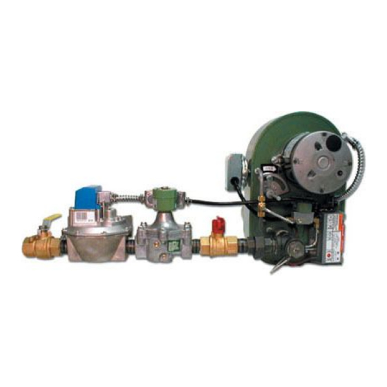
- Page 7 Part 1 Installation Part 1 Installation Continued RE4850BA UL, Valve Train Assembly 24VAC Figure 5: Piping Diagram (Continued)
-
Page 8: Input Selection
Part 1 Installation ? When the burner is installed in the vestibule of jacketed equipment, it is recommended that Part 1 the Automatic Safety Shut-Off Valves be left adjacent to the burner within the vestibule and the Installation Main Manual Shut-Off Valve be installed outside. Continued ? Run full size pipe or tubing from regulator vent openings to outside of building. - Page 9 Part 1 Installation Part 1 Natural Gas / Propane Gas Orifice Size and Pressure Settings Installation RE4850BA Natural Gas Propane Gas Continued Input Orifice Manifold Orifice Manifold Pressure Pressure MBTU/HR Size Letter Size Letter VIII Initial Start- ("W.C) ("W.C) (Inches) Stamp (Inches) Stamp...
- Page 10 Part 1 Installation Part 1 To make a preliminary setting of the burner input, determine the manifold gas pressure required from Table 3 and adjust the Main Gas Pressure Regulator accordingly. See Installation Section XI. Continued To determine the firing rate for NATURAL gas, accurately time test dial for the number of seconds for one revolution and use the following formula.
- Page 11 Part 1 Installation Part 1 manual; and the carbon dioxide content should be approximately 9.5% for NATURAL or 12% for propane , or within the limits prescribed by local codes. Installation Continued 12. Check the draft control to make sure there is no spillage of flue products into the room. 13.
- Page 12 Part 2 Service The pilot is of the premix, blast type. The full force of blower air is brought into the mixing tube Part 2 where the proper amount of gas is added through the pilot orifice. This mixture is discharged Service Continued through the pilot.
-
Page 13: Valve Train
Part 2 Service Part 2 ? To make a specific test of the interlock circuit: Turn burner power OFF. Service Continued Turn Manual Gas Cock OFF. Motor Blower Disconnect the motor wire from the terminal strip to keep the motor off. Turn burner power ON and set the operating control to ON or thermostat to call for Interlock heat. -
Page 14: Part 3 Maintenance
Part 3 Maintenance CONSUMER INSTRUCTIONS Part 3 ? Keep the area around the burner clear and free of combustible material, gasoline or other Maintenance flammable liquids or vapors. Do not obstruct burner air openings or ventilation grills for combustion air. ? The motor features permanently lubricated ball bearings and requires no maintenance. -
Page 15: Part 3 Trouble Chart
Part 3 Trouble Chart Part 3 TROUBLE CHART Continued Make sure the thermostat and operating controls are calling for heat. Trouble Chart CAUTION: If a test indicates an electrical component may be defective, before replacing it, make sure that its associated wiring is not at fault. ELECTRICAL AND FLAME CHECKS MUST BE MADE IN THE ORDER LISTED BELOW. - Page 16 Midco International Inc. 4140 West Victoria Street * Chicago, Illinois 60646 1201 tel 773.604.8700 fax 773.604.4070 web www.midco-intl.com email sales@midco-intl.com 8471 24 Printed in USA...
Need help?
Do you have a question about the economite RE4850BA and is the answer not in the manual?
Questions and answers