Table of Contents
Advertisement
Harbor Breeze
®
is a registered trademark
of LF, LLC. All Rights Reserved.
ATTACH YOUR RECEIPT HERE
Serial Number
Questions, problems, missing parts? Before returning to your retailer, call our customer
service department at 1-800-643-0067, 8 a.m. - 6 p.m., EST, Monday - Thursday,
8 a.m. - 5 p.m., EST, Friday.
EB14464
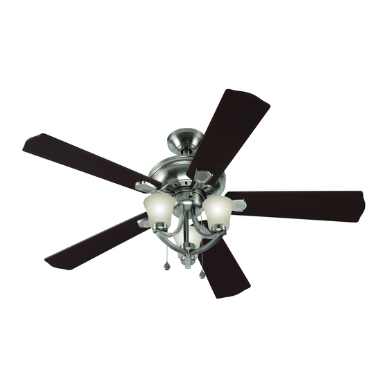
BAY BRIDGE CEILING FAN
Purchase Date
1
ITEM #0451817
MODEL #CPJ1240
Español p. 19
Lowes.com/harborbreeze
Advertisement
Table of Contents

Subscribe to Our Youtube Channel
Summary of Contents for Harbor Breeze CPJ1240
- Page 1 ITEM #0451817 BAY BRIDGE CEILING FAN MODEL #CPJ1240 Harbor Breeze ® is a registered trademark Español p. 19 of LF, LLC. All Rights Reserved. ATTACH YOUR RECEIPT HERE Purchase Date Serial Number Questions, problems, missing parts? Before returning to your retailer, call our customer service department at 1-800-643-0067, 8 a.m.
-
Page 2: Table Of Contents
TABLE OF CONTENTS Package Contents ....................... Hardware Contents ......................Safety Information ....................... Preparation .......................... Initial Instructions........................Standard/Angle-Mounting Instructions ................. Flushmount Instructions ....................... Wiring Instructions ....................... Final Instructions ......................... Operating Instructions ......................Care and Maintenance ......................Troubleshooting ........................Limited Lifetime Warranty ....................Replacement Parts List ....................... -
Page 3: Package Contents
PACKAGE CONTENTS PART DESCRIPTION QUANTITY Mounting Bracket Canopy Canopy Cover (preassembled on Canopy (B)) Downrod Assembly Coupling Cover Coupling (preassembled to Motor Housing (G)) Motor Housing Switch Housing (preassembled to Motor Housing (G)) Blade Iron Blade Light Kit Glass Bowl Bulb Clevis Pin (preassembled to Coupling (F)) Hairpin Clip (preassembled to Coupling (F)) -
Page 4: Hardware Contents
HARDWARE CONTENTS lade Scre Wire onnector Qt . 5 + e tra Qt . Qt . 2 otor Scre Qt . 2 SAFETY INFORMATION READ AND SAVE THESE INSTRUCTIONS Please read and understand this entire manual before attempting to assemble, operate or install the product. surface. -
Page 5: Preparation
WARNING Risk of fire. Most dwellings built before 1985 have supply wire rated for 140°F. Consult a qualified electrician before installation. To reduce the risk of fire or electric shock, do not use this fan with any solid state fan speed device or variable speed control. -
Page 6: Initial Instructions
INITIAL INSTRUCTIONS 1. Turn off circuit breakers and wall switch to the fan supply line leads. DANGER: Failure to disconnect power supply prior to installation may result in serious injury or death. 2a. Choose the desired mounting method: A. Standard Mounting: Standard mounting is best suited for ceilings 8 ft. -
Page 7: Standard/Angle-Mounting Instructions
INITIAL INSTRUCTIONS 3. Check existing outlet box (not included) to ensure it is securely fastened to at least two points in a structural ceiling member and can support the full weight of the fan. Once verified, install mounting bracket (A) to the outlet box using the screws and washers provided with the outlet box. - Page 8 STANDARD/ANGLE-MOUNTING INSTRUCTIONS 2. Feed power wires from motor housing (G) through downrod assembly (D), then insert downrod assembly (D) into the coupling (F) on motor housing (G). Align the hole on downrod assembly (D) to hole on coupling (F), then re-install clevis pin (N). Re-attach hairpin clip (O) into clevis pin (N) until it snaps into place, then tighten the two previously loosened coupling screws (P).
-
Page 9: Flushmount Instructions
FLUSHMOUNT INSTRUCTIONS 1. Press out on the inner edges of the canopy cover (C) from inside the canopy (B) until it releases from the canopy (B). Note: Flushmount installation will not use canopy cover (C), downrod assembly (D), coupling cover (E), clevis pin (N), hairpin clip (O) or coupling screws (P). -
Page 10: Wiring Instructions
WIRING INSTRUCTIONS WARNING: To avoid possible electrical shock, be sure electricity is turned off at the main fuse box before hanging. WARNING: If you are not sure if the outlet box is grounded, contact a licensed electrician for advice, as it must be grounded for safe operation. WARNING: If house wires are of different colors than referred to in the following steps, stop immediately. -
Page 11: Final Instructions
WIRING INSTRUCTIONS 3. Wrap electrical tape (not included) around each wire connector (AA) and make sure no bare wire or wire Outlet Box strands are visible after making connections. Then, turn wires upward and carefully push them into GREEN the outlet box; make sure the WHITE and GREEN connections are on one side and the BLACK connections are on the other side. - Page 12 FINAL INSTRUCTIONS 3. Loosen (do not remove) the motor screws (T) from motor housing (G) and discard the preassembled motor blocks. Slide the blade assemblies onto motor Motor Block housing (G) and tighten the motor screws (T) securely. Note: If you misplace one or two motor screws during installation of the blade assemblies, use the extra motor screws (CC) instead.
- Page 13 FINAL INSTRUCTIONS 6. Remove socket ring (U) from each socket on light kit (K). 7. Slide glass bowl (L) to each socket, securing with socket rings (U). 8. Install bulbs (M) into each socket. CAUTION: If you replace the bulbs (M) with more than 190 watts, the fixture will automatically turn off.
-
Page 14: Operating Instructions
FINAL INSTRUCTIONS 9. Connect the fobs (DD) to the appropriate pull chains. Hardware Used OPERATING INSTRUCTIONS 1. The fob (DD) marked with a fan image is for motor speed control: High, Medium, Low and Off. Pull once for each position. The fob (DD) marked with a lamp image controls the light, either ON or OFF with each pull of the chain. -
Page 15: Care And Maintenance
CARE AND MAINTENANCE Important: Shut off main power supply before beginning any maintenance. Do not use water or a damp cloth to clean the ceiling fan. At least twice each year, tighten all screws and lower canopy to check mounting plate screws. Clean fan housing with only a soft brush or lint-free cloth to avoid scratching the finish. - Page 16 TROUBLESHOOTING PROBLEM PROBABLE CAUSE CORRECTIVE ACTION 6. Blade holders are loose. 6. Check to be sure the fan blade irons seat firmly and uniformly on the surface of the motor. If flanges are seated incorrectly, loosen the flange screws and retighten. 7.
-
Page 17: Limited Lifetime Warranty
LIMITED LIFETIME WARRANTY The manufacturer warrants this fan to be free from defects in workmanship and material present at time of shipment from the factory for life (with limitations) from the date of purchase. This warranty applies only to the original purchaser. The manufacturer agrees to correct such defect at no charge or, at our option, replace the ceiling fan with a comparable or superior model. -
Page 18: Replacement Parts List
Blade A141-0370036 Light Kit A187-0288084 Glass Bowl A182-0287036 Socket Ring B172-0036045 Locking Ring Tool B171-0273005 Wire Connector Blade Screw B168-0387018 Extra Motor Screw Printed in China Harbor Breeze is a registered trademark of LF, LLC. All Rights Reserved. ® Lowes.com/harborbreeze...
Need help?
Do you have a question about the CPJ1240 and is the answer not in the manual?
Questions and answers