Table of Contents
Advertisement
Your new tool has been engineered and manufactured to WEN's highest standards for dependability,
ease of operation, and operator safety. When properly cared for, this product will supply you years
of rugged, trouble-free performance. Pay close attention to the rules for safe operation, warnings,
and cautions. If you use your tool properly and for intended purpose, you will enjoy years of safe,
reliable service.
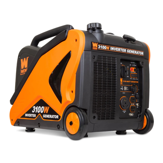
3100W INVERTER
GENERATOR
IMPORTANT:
NEED HELP? CONTACT US!
Have product questions? Need technical support?
Please feel free to contact us at:
800-232-1195
techsupport@wenproducts.com
WENPRODUCTS.COM
Model # 56310i
bit.ly/WENvideo
(M-F 8AM-5PM CST)
Advertisement
Table of Contents

Related Manuals for Wen 56310i

Summary of Contents for Wen 56310i
- Page 1 IMPORTANT: Your new tool has been engineered and manufactured to WEN’s highest standards for dependability, ease of operation, and operator safety. When properly cared for, this product will supply you years of rugged, trouble-free performance. Pay close attention to the rules for safe operation, warnings, and cautions.
-
Page 2: Table Of Contents
TABLE OF CONTENTS Generator Identification Service Record Introduction Safety Information General Safety Procedures Important Safety Instructions Generator Components Generator Preperation Starting the Generator Stopping the Generator Subsequent Starting of the Generator Using the Generator Maintenance & Care Storage & Transport Specifications Troubleshooting Exploded View and Parts List... -
Page 3: Generator Identification
GENERATOR IDENTIFICATION If assistance for information or service is required, please contact the Customer Service Help Line by calling 800-232-1195; customer will be asked to provide generator information when calling. Refer to the illustration below for the location of the serial number. Record generator information in the spaces provided below. -
Page 4: Introduction
Every effort has been made to ensure the accuracy of the information in this manual. WEN® reserves the right to change this product and specifications at any time without prior notice. Please keep this manual available to all users during the entire life of the generator. -
Page 5: General Safety Procedures
GENERAL SAFETY PROCEDURES For any questions regarding the hazard and safety notices listed in this manual or on the product, please call (800) 232-1195 M-F 8-5 CST before using the generator. DANGER: CARBON MONOXIDE Using a generator indoors CAN KILL YOU IN MINUTES. Generator exhaust contains carbon monoxide (CO). This is a poison gas you cannot see or smell. -
Page 6: Important Safety Instructions
Turn the engine switch to “OFF” position when the engine is not running. IMPORTANT SAFETY INSTRUCTIONS SAVE THESE INSTRUCTIONS – This manual contains important instructions for the WEN inverter generator that should be followed during installation and maintenance of the generator. -
Page 7: Generator Components
GENERATOR COMPONENTS Use the illustrations below to become familiar with the locations and functions of the various components and controls of this generator. Carrying Handle Handles Lock Recoil Handle Fuel Tank Control Panel Wheel Slats... -
Page 8: Generator Preperation
GENERATOR PREPARATION USING THE GENERATOR FOR THE FIRST TIME The following section describes steps necessary to prepare the generator for use. If after reading this sec- tion, you are unsure about how to perform any of the steps please call (800) 232-1195 M-F 8-5 CST for customer service. - Page 9 GENERATOR PREPARATION Step 2 - ADD GASOLINE WARNING: This generator may emit highly flammable and explosive gasoline vapors, which can cause severe burns or even death if ignited. A nearby open flame can lead to explosion even if not directly in contact with gasoline. Use fresh (within 30 days from purchase), lead-free gasoline with a minimum of 87 octane rating.
-
Page 10: Starting The Generator
STARTING THE GENERATOR Before starting the generator, make sure you have read and performed the steps in the “Generator Preperation” section of this manual. If you are unsure about how to perform any of the steps in this manual please call (800) 232-1195 M-F 8-5 CST for customer service. - Page 11 STARTING THE GENERATOR STARTING THE ENGINE To start the generator, perform the following steps: 1. Unplug all electrical devices from the generator during starting. Otherwise it can be difficult for the engine to start. 2. Check that the generator is properly grounded (Refer to “Ground the Generator”). 3.
-
Page 12: Stopping The Generator
STOPPING THE GENERATOR TO STOP THE GENERATOR 1. Turn off all electrical devices prior to unplugging them from the generator. Unplugging running devices can cause damage to the generator. 2. Turn the 3-in-1 knob to the “OFF” position. 3. Close the vacuum relief valve on top of fuel cap. Rotate counterclockwise to the “OFF” position. WARNING: Allow the generator to cool for several minutes before touching areas that become hot during use. - Page 13 SUBSEQUENT STARTING OF THE GENERATOR Step 2 - CHECK THE FUEL LEVEL Before starting the generator, check to see that there is sufficient gasoline in the fuel tank. Add additional gasoline as necessary but leave sufficient room in tank for expansion. WARNING: This generator may emit highly flammable and explosive gasoline vapors, which can cause severe burns or even death if ignited.
-
Page 14: Using The Generator
The surge wattage ability of the generator covers this extra power requirement. Item Rated (Running) Wattage Surge Wattage 56310i 2800 3100 Figure 6 - Generator Wattage The total running wattage requirement of the electrical devices connected to the generator should not exceed the rated wattage of the generator itself. - Page 15 USING THE GENERATOR CAUTION: The generator can run at its surge wattage capacity for only a short time. Connect electrical devices requiring a rated (running) wattage equal to or less than the rated wattage of the generator. Never connect devices requiring a rated wattage equal to the surge wattage of the generator.
- Page 16 USING THE GENERATOR CAUTION: Do not connect 50Hz loads to the generator. SOME NOTES ABOUT POWER CORDS Long or thin cords can drain the power provided to an electrical device by the generator. When using such cords, allow for a slightly higher rated wattage requirement by the electrical device. See Figure 8 for recommended cords based on the power requirement of the electrical device.
-
Page 17: Maintenance & Care
MAINTENANCE & CARE CLEANING THE GENERATOR Never clean the generator when it is running! Never clean with a bucket of water or a hose. Water can get inside the working parts of the generator and cause a short circuit or corrosion. Always try to use the generator in a cool, dry place. - Page 18 MAINTENANCE & CARE To refill the crankcase with oil, follow these steps: 1. Make sure the generator is on a level surface. Tilting the generator to assist in filling will cause oil to flow into engine areas and will cause damage. Keep generator level! 2.
- Page 19 MAINTENANCE & CARE SPARK PLUG MAINTENANCE The spark plug is important for proper engine operation. A good spark plug should be intact, free of deposits, and properly gapped. Refer to Recommended Maintenance Schedule in Figure 9. To inspect the spark plug: 1.
-
Page 20: Storage & Transport
MAINTENANCE & CARE DRAINING THE FUEL TANK Clean fuel tank each year or before storing the generator for extended periods of time. To drain the fuel tank and carburetor: 1. Remove the fuel cap; carefully turn the generator over to pour the gasoline in the fuel tank to appropriate con- tainer. -
Page 21: Specifications
SPECIFICATIONS DC output Rated Voltage 12 VDC Rated Amperage 8.3 A Rated Wattage 100 W USB Charger 5V, 1 A & 2.1 A AC output Rated Wattage 2800 Watts Surge Wattage 3100 Watts Rated Voltage 120 V Rated Amperage 23.3 A Frequency 60 Hz Phase... -
Page 22: Troubleshooting
TROUBLESHOOTING IMPORTANT: If trouble persists, please call our customer help line at (800) 232-1195 M-F 8-5 Central Time. Problem Problem Cause Cause Solution Solution Engine will not start Engine will not start Engine switch in “OFF” position Set engine switch to “CHOKE” position. Engine switch in “OFF”... -
Page 23: Exploded View And Parts List
EXPLODED VIEW AND PARTS LIST FIG.1 CYLINDER HEAD ASSEMBLY Item Stock # Description FIG01-1 56310i-0101 BOLT FIG01-2 56310i-0102 COVER SUBASSEMBLY, CYLINDER HEAD FIG01-3 56310i-0103 GASKET, CYLINDER HEAD COVER FIG01-4 56310i-0104 PLUG, SPARK FIG01-5 56310i-0105 SHROUD, CYLINDER BODY FIG01-6 56310i-0106 BOLT, CYLINDER HEAD... - Page 24 EXPLODED VIEW AND PARTS LIST FIG.2 CRANKCASE ASSEMBLY Item Stock # Description FIG02-1 56310i-0201 CRANKCASE SUBASSEMBLY. FIG02-2 56310i-0202 WASHER FIG02-3 56310i-0203 BOLT, DRAIN PLUG FIG02-4 56310i-0204 PLUG, END FIG02-5 56310i-0205 BEARING FIG02-6 56310i-0206 OIL-SEAL FIG02-7 56310i-0207 BOLT FIG02-8 56310i-0208 CLAMP, GENERATOR LEAD WIRE...
- Page 25 EXPLODED VIEW AND PARTS LIST FIG.3 CRANKCASE COVER Item Stock # Description FIG03-1 56310i-0301 COVER, CRANKCASE FIG03-2 56310i-0302 DIPSTICK SUBASSEMBLY, OIL FIG03-3 56310i-0303 FIG03-4 56310i-0304 BEARING FIG03-5 56310i-0305 GASKET, CRANKCASE FIG03-6 56310i-0306 OIL-SEAL FIG03-7 56310i-0307 BOLT FIG.4 CRANKSHAFT Item Stock #...
- Page 26 EXPLODED VIEW AND PARTS LIST FIG.5 CONNETING ROD Item Stock # Description FIG05-1 56310i-0501 RING ASSY, PISTON FIG05-2 56310i-0502 ROD, CONNECTING FIG05-3 56310i-0503 PISTON FIG05-4 56310i-0504 PIN, PISTON FIG05-5 56310i-0505 CLIP, PISTON PIN...
- Page 27 EXPLODED VIEW AND PARTS LIST FIG.6 VALVES, CAMSHAFT ASSEMBLY Item Stock # Description FIG06-1 56310i-0601 CAMSHAFT ASSY. FIG06-2 56310i-0602 valve FIG06-3 56310i-0603 GUIDE, SEAL FIG06-4 56310i-0604 SPRING, VALVE FIG06-5 56310i-0605 SEAT, VALVE SPRING FIG06-6 56310i-0606 CLAMP, VALVE LOCK FIG06-7 56310i-0607...
- Page 28 EXPLODED VIEW AND PARTS LIST FIG.7 RECOIL STARTER Item Stock # Description FIG07-1 56310i-0701 STARTER, RECOIL FIG07-2 56310i-0702 BOLT FIG07-3 56310i-0703 GUIDE , STARTING ROPE FIG07-4 56310i-0704 HANDLE, RECOIL STRATER CABLE FIG07-5 56310i-0705 BOLT FIG07-6 56310i-0706 PULLEY,STARTER FIG07-7 56310i-0707 SEAT, STARTER CUP...
- Page 29 EXPLODED VIEW AND PARTS LIST FIG.9 AIR CLEANER Item Stock # Description FIG09-1 56310i-0901 GASKET, AIR CLEANER FIG09-2 56310i-0902 FIG09-3 56310i-0903 CLEANER, AIR FIG.10 MUFFLER Item Stock # Description FIG10-1 56310i-1001 BOLT FIG10-2 56310i-1002 SHROUD FIG10-3 56310i-1003 IMPELLER FIG10-4 56310i-1004...
- Page 30 EXPLODED VIEW AND PARTS LIST FIG.11 FLYWHEEL AND IGNITION COIL Item Stock # Description FIG11-1 56310i-1101 NUT, FLYWHEEL FIG11-2 56310i-1102 IMPELLER FIG11-3 56310i-1103 SCREW FIG11-4 56310i-1104 ROTOR COMP FIG11-5 56310i-1105 STATOR COMP. FIG11-6 56310i-1106 BOLT FIG11-7 56310i-1107 TRIGGER ASSY. FIG11-8...
- Page 31 EXPLODED VIEW AND PARTS LIST FIG.12 FRAME Item Stock # Description FIG12-1 56310i-1201 BOLT FIG12-2 56310i-1202 FRAME ASSY, ENGINE(RIGHT) FIG12-3 56310i-1203 FRAME ASSY, ENGINE(LEFT) FIG12-4 56310i-1204 LASSO COMP. FIG12-5 56310i-1205 SPRING FIG12-6 56310i-1206 FIG12-7 56310i-1207 CROSS-HEAD SCREW FIG12-8 56310i-1208 BUSH...
- Page 32 EXPLODED VIEW AND PARTS LIST FIG.13 PLASTIC COVER Item Stock # Description FIG13-1 56310i-1301 FIG13-2 56310i-1302 BOLT FIG13-3 56310i-1303 CROSS-HEAD SCREW AND WASHER COMP. FIG13-4 56310i-1304 SHAFT, FRONT WHEEL FIG13-5 56310i-1305 WHEEL BODY,FRONT FIG13-6 56310i-1306 RIGHT SHELL FIG13-7 56310i-1307 RIGHT PANEL...
- Page 33 EXPLODED VIEW AND PARTS LIST FIG.14 BASE AND INVERTER Item Stock # Description FIG14-1 56310i-1401 PLATE, BOTTOM FIG14-2 56310i-1402 SEAT,FRAME FIG14-3 56310i-1403 BOLT FIG14-4 56310i-1404 FIG14-5 56310i-1405 BOLT FIG14-6 56310i-1406 AIR FILTER INLET COMP. FIG14-7 56310i-1407 FIG14-8 56310i-1408 FIG14-9 56310i-1409...
- Page 34 EXPLODED VIEW AND PARTS LIST FIG.15 SHROUD Item Stock # Description FIG15-1 56310i-1501 STRIP, SHROUD SEAL FIG15-2 56310i-1502 COVER, MUFFLER OUTER FIG15-3 56310i-1503 CROSS-HEAD SELF-TAPPING SCREW FIG15-4 56310i-1504 MUFFLER INSULATION GASKET FIG15-5 56310i-1505 COVER, MUFFLER SIDE FIG15-6 56310i-1506 CROSS-HEAD SCREW AND WASHER COMP.
- Page 35 EXPLODED VIEW AND PARTS LIST FIG.16 CONTROL PANEL Item Stock # Description FIG16-1 56310i-1601 PANEL, CONTROL,ASSY. FIG16-2 56310i-1602 IDLE SWTICH FIG16-3/4 56310i-1603 PARALLEL KIT FIG16-5 56310i-1605 IGNITOR FIG16-6 56310i-1606 USB OUTPUT FIG16-7 56310i-1607 SOCKET SUBASSEMBLY, D.C FIG16-8 56310i-1608 BREAKER FIG16-9...
- Page 36 EXPLODED VIEW AND PARTS LIST FIG.17 FUEL TANK Item Stock # Description FIG17-1 56310i-1701 BOLT FIG17-2 56310i-1702 COVER, FUEL TANK FIG17-3 56310i-1703 FUEL FILTER FIG17-4 56310i-1704 SLEEVE, FILLING OIL HOLE RUBBER FIG17-5 56310i-1705 FUEL FILTER FIG17-6 56310i-1706 TANK, FUEL FIG17-7...
- Page 37 EXPLODED VIEW AND PARTS LIST FIG.18 HANDLE Item Stock # Description FIG18-1 56310i-1801 HANDLE FIG18-2 56310i-1802 HANDLE FIG18-3 56310i-1803 BLOT FIG18-4 56310i-1804 SCREW FIG18-5 56310i-1805 ROTOR ARM FIG18-6 56310i-1806 ROTOR ARM FIG18-7 56310i-1807 NYLON NUT FIG18-8 56310i-1808 BLOT FIG18-9 56310i-1809...
-
Page 39: Warranty Statement
WEN® will repair or replace, at its discretion, any part that is proven to be defective in materials or workman- ship under normal use during the two (2) years warranty period. Warranty repairs or replacements will be made without charge for parts or labor. - Page 40 Thanks for remembering...
Need help?
Do you have a question about the 56310i and is the answer not in the manual?
Questions and answers