
Summary of Contents for Fox F36-258DB
- Page 1 DOUBLE BEVEL RADIAL MITRE SAW with Laser Saw blade’s diameter 255 mm (FOX model F36-258DB)
- Page 2 Double bevel sliding mitre saw (F36-258 DB model) INDEX • Safety instructions • General safety instructions • Specific safety instructions for radial mitre saws • Safety instruction for the laser pointing device • Environment protection • Symbols • Electrical connections •...
-
Page 3: Safety Instructions
SAFETY INSTRUCTIONS CAUTION: Besides following the instructions mentioned in this manual, when using electric equipment you must always observe all safety precautions to prevent risk of fire, electric shock and personal injury. Read this instruction manual before use and keep it carefully. Working with power tools can be dangerous if you do not follow suitable safety measures. -
Page 4: General Safety Instructions
Do not force the machine. You can obtain better and safer results if you use the machine at the cutting pressure for which it has been designed. Use the suitable tool. Do not use a small tool for an intensive job. Fox example, do not use a circular saw to cut branches or stumps. - Page 5 Block the piece. If possible, use C-clamps or a holder to fix the piece. It is safer than using only your hands. Keep the tools in perfect conditions. Keep the tools sharp and clean to obtain better and safer results. Follow the instructions to grease and change the accessories. Check regularly the electric cable and change it if it is damaged.
- Page 6 SPECIFIC SAFETY INSTRUCTIONS FOR RADIAL MITRE SAWS ALWAYS DISCONNECT the mitre saw from the socket before replacing the saw blade and before any fixing, cleaning or maintenance work or any kind of intervention. DO NOT START the mitre saw until it has been completely assembled and installed according to the instructions of this manual, until all the protection devices are assembled and working and all locking handles are correctly tighten.
- Page 7 BE SURE that the saw blade does not touch the work-piece before starting cutting. LET the motor reach its maximum range of speed before starting to cut. BE SURE that the saw blade is completely still before moving or locking the piece to be cut, changing the angle at which the piece is placed or changing saw blade’s angle.
- Page 8 ENVIRONEMENT PROTECTION INFORMATION FOR USERS In accordance with art. 13 of Legislative Decree 25th July 2005, no. 151 “Implementation of Directives 2002/95/EEC, 2002/96/EEC and 2003/108/EEC, relative to reducing the use of hazardous substances in electric and electronic appliances and the disposal of waste”, please take note of the following: •...
-
Page 9: Electrical Connections
Product in compliance with relative CE regulations. Double insulation. This symbol means that you cannot get at any element without using a tool. Tools which have this symbol have not any earthing protection systems. Indicates that this machine is equipped with a laser pointing device (see par. SAFETY INSTRUCTIONS FOR THE POINTING DEVICE). -
Page 10: Recommended Use
WARNING: KEEP THE TOOLS AND THE EQUIPMENT AT A SAFE DISTANCE FROM CHILDREN RECOMMENDED USE This tool has been designed for cross and radial cutting wood and similar materials. With the saw blade in a vertical position the maximum cutting height is 105 mm and the maximum cutting width is 340 mm. - Page 11 there is a connection between emission levels and exposure levels, the first ones cannot be used to determine safely if other precautions are necessary. The factors that can influence the actual exposure level of the operator include the exposure length, environment features and other sources of noise, as for example the number of machines and operations present.
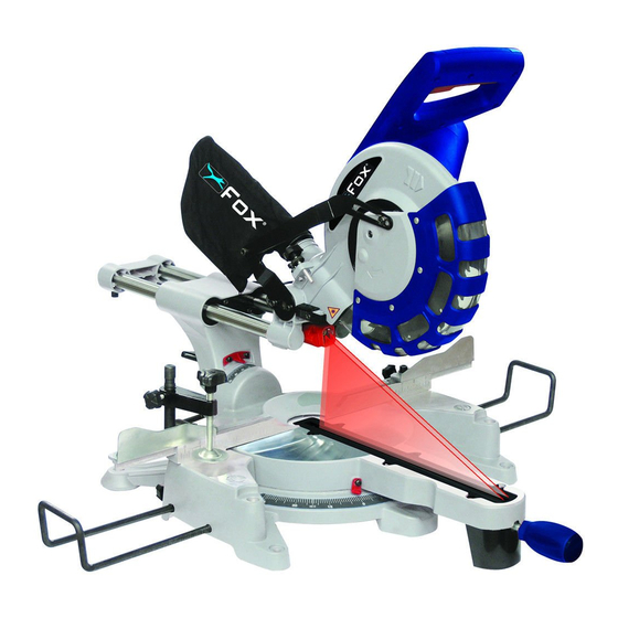
- Page 12 SLIDING MITRE SAW IDENTIFICATION Fig.2 A. Operating Handle B. Laser on-off switch C. Starter trigger D. Lower Blade protection E. Blade F. Double beam Laser G. Extensible supports H. Rotating base J. Bevel cut rotation handle K. Rotating base graduation L.
-
Page 13: Using The Clamp
ASSEMBLY CAUTION! Be sure that the mitre saw is switched off and disconnected from any current source before assembly or any kind of adjustment. ASSEMBLY OF THE ROTATING BASE HANDLE Before using your double bevel mitre saw, you have to assemble the rotating base handle (J) Fig.2. - Page 14 ASSEMBLING THE EXTENSIBLE SUPPORTS The mitre saw is equipped with two lateral extensible supports (A) Fig.5 useful to support long work-pieces during the cut. These supports can be assembled on both sides machine, depending dimensions of the work-piece. Unscrew the knob (B), insert the extensions into the slots on both sides of the base and Fig.5 lock the knobs again.
- Page 15 CUT-END GUIDE EXTENSIONS The cut-end guide can be extended on both sides in case of wide work-pieces. To do this: Loosen hexagonal screw Fig.8 with a hexagonal wrench. Loosen the knob (C). Slide the extension (A) on the desired position and tight the screw (B), then the knob (C).
- Page 16 SETTING THE CUT-END GUIDE FOR 90° CUT Make sure that the disk is perpendicular to the guide Block the mitre saw’s head in the low position, close the lock-knob in the transport position (see Fig.1). Loosen the base rotation knob and position it at 0°. Re-tighten the base rotation knob. Loosen the head bevel knob located on the back of the machine and set the position the head at 0°.
- Page 17 on each side of the head bevel knob) to release the two bolts (B). • Loosen the head bevel knob (C) and pull the spindle (D) towards you. • Position the square against the table. • Adjust the two bolts (B) modifying the inclination, until the two sides of the square are in continuous contact with disk and table.
-
Page 18: Setting The Cutting Depth
SETTING THE CUTTING DEPTH The vertical depth of the cut can be adjusted, allowing the mitre saw to cut a groove When setting the cutting depth make sure that the disk may not touch the base, in the lower position; the disk could damage the base. - Page 19 Connect the feeder cable to the electric socket. Press ON button (2) Fig.1 to start the mitre saw. Release the ON button to stop the mitre saw. WARNING! Do not cut short work-pieces: a too short piece won’t allow you to keep your hands at a safe distance from the disk.
- Page 20 Lift up the arm to the upper position. To block the arm in the lower position: Lower down the arm to the lower position. Pull and turn the knob (A) Fig.16. Fig.16 HANDS AND FEET POSITION Your cut will be easier and safer if you adopt a correct hands and body’s working position. Stand on the side of the machine, do not stand on the line of the chips ejection.
- Page 21 press the trigger to start the machine and wait until the disk has reached its maximum speed. Slowly lower the disk through the piece and let the disk slide in the opposite direction to cut all along the piece. Do not put high pressure on the disk: your cut will be more efficient and precise if the disk turns at the correct speed.
-
Page 22: Bevel Cutting
WARNING! If you cut the wrong way, the piece could suddenly move and cause injuries to the user. ANGLE CUTTING Lift the arm to the upper position. release the base rotation knob and turn the base according to the desired angle, holding the operating handle. - Page 23 PROFILE (MOPBOARD) CUTTING You can cut profiles and mopboards. Use a clamp whenever possible. Protect the surface in contact with the clamp, using a wood-piece. Select the preferred cut direction, to prevent cutting from scraping mopboard. Worktable Worktable Do as many test-cuts as reasonable before cutting definitely.
-
Page 24: Wood Chips
MAINTENANCE WARNING! - Before any repair or maintenance on the machine, disconnect the feeder cable. This has to remain disconnected every time you set or repair the machine. - To prevent electrical shocks and fire, always use spare parts with the same characteristics - Used, cut or damaged cables have to be immediately replaced WOOD CHIPS... - Page 25 INSPECTION AND REPLACEMENT OF MOTOR BUSHES WARNING: Before inspecting the brushes disconnect the feeder cable. Brushes’ duration is variable. It depends on the amount of work done by the motor. Verify the brushes after the first 20 hours of use of a new machine or after mounting new brushes. After the first check, inspect them every 10 hours of work, until the replacement becomes necessary.
- Page 26 Lift up the head. Lift the lower disk protection (A) Fig.19 with one hand while with the other hand you unscrew the two screws blocking the disk protection plate (C) and connecting the disk lower protection to the disk upper protection (D). Pull the plate towards the table keeping the blade protection on the lower, then lay everything on the table.
- Page 27 DUNNIKIER BUINESS PARK KIRKCALDY, UK, KY1 3PD Tel. +44 (0) 1592 652946 Fax: +44 (0) 1592 654854 Declares that the: SLIDING MITRE SAW (F36-258DB) is in compliance with the regulations included in the Directives: CEE 2006/42-2004/108-2006/95 EC DECLARATION OF CONFORMITY Certificate for EC-type examination delivered by TÜV Rheinland Product Safety GmbH –...
- Page 28 F36-258DB DOUBLE BEVEL SLIDING MITRE SAW...
- Page 29 F36-258DB DOUBLE BEVEL SLIDING MITRE SAW 59 F36258DB-59 117 F36258DB-117 175 F36258DB-175 1 F36258DB-1 60 F36258DB-60 118 F36258DB-118 176 F36258DB-176 2 F36258DB-2 61 F36258DB-61 119 F36258DB-119 177 F36258DB-177 3 F36258DB-3 62 F36258DB-62 120 F36258DB-120 178 F36258DB-178 4 F36258DB-4 5 F36258DB-5...
-
Page 30: Wiring Diagram
WIRING DIAGRAM...
Need help?
Do you have a question about the F36-258DB and is the answer not in the manual?
Questions and answers