Table of Contents
Advertisement
Quick Links
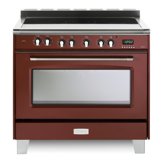
ELECTRIC RANGE
for residential use only
VCLFSEE 365 ..
Models:
USERS OPERATING INSTRUCTIONS
IMPORTANT - PLEASE READ AND FOLLOW
• Before beginning, please read these instructions completely and carefully.
• Do not remove permanently affixed labels, warnings, or plates from the product. This may
void the warranty.
• Please observe all local and national codes and ordinances.
• Please ensure that this product is properly grounded.
• The installer should leave these instructions with the consumer who should retain
for local inspector's use and for future reference.
Electrical installation must be in accordance with the National Electrical Code, ANSI/NFPA70
- latest edition and/or local codes.
IN CANADA: Electrical installation must be in accordance with the current CSA C22.1
Canadian Electrical Codes Part 1 and/or local codes.
Some models are supplied with a protective film on steel and aluminium
parts. This film must be removed before installing/using the appliance.
THIS RANGE IS FOR RESIDENTIAL USE ONLY
R
Advertisement
Table of Contents

Summary of Contents for Verona VCLFSEE 365 Series
- Page 1 ELECTRIC RANGE for residential use only VCLFSEE 365 .. Models: USERS OPERATING INSTRUCTIONS IMPORTANT - PLEASE READ AND FOLLOW • Before beginning, please read these instructions completely and carefully. • Do not remove permanently affixed labels, warnings, or plates from the product. This may void the warranty. • Please observe all local and national codes and ordinances. • Please ensure that this product is properly grounded. • The installer should leave these instructions with the consumer who should retain for local inspector’s use and for future reference.
- Page 2 WARNING ! To reduce the risk of tipping the appliance, the appliance must be secured by properly installed anti-tip device packed with the appliance. • ALL RANGES CAN TIP • INJURY TO PERSONS COULD RESULT • INSTALL ANTI-TIP DEVICE PACKED WITH RANGE • SEE INSTALLATION INSTRUCTIONS...
- Page 3 Dear Customer, Thank you for having purchased and given your preference to our product. The safety precautions and recommendations reported below are for your own safety and that of others. They will also provide a means by which to make full use of the features offered by your appliance. Please preserve this booklet carefully.
-
Page 4: General Information
USER INSTRUCTIONS GENERAL INFORMATION IMPORTANT PRECAUTIONS RECOMMENDATIONS After having unpacked the appliance, check to ensure that it is not WARNING!! 1. damaged. This appliance shall not be used for space heating. This In case of doubt, do not use it and consult your supplier or a information is based on safety considerations. professionally qualified technician. Packing elements (i.e. plastic bags, polystyrene foam, nails, 2. AlI openings in the wall behind the appliance and in the floor packing straps, etc.) should not be left around within easy reach under the appliance shall be sealed. - Page 5 IMPORTANT PRECAUTIONS AND RECOMMENDATIONS FOR USE OF ELECTRICAL APPLIANCES Use of any electrical appliance implies the necessity to follow a series of fundamental rules. In particular: • Never touch the appliance with wet hands or feet. • Do not operate the appliance barefooted. • Do not allow children or disabled people to use the appliance without your supervision. The manufacturer cannot be held responsible for any damages caused by improper, incorrect or unreasonable use of the appliance. WARNING – VERY IMPORTANT ! FIRE/OVERHEATING HAZARD: • Do not place towels/cloths etc onto the hob rail or oven door handle/s whilst the product is in use or hot. TO AVOID DAMAGE TO THE APPLIANCE: • Do not lift/move the cooker by the hob rail or oven door handle/s.
- Page 6 features 3” Backguard fitted 8” Backguard fitted WARNING - VERY IMPORTANT NOTICE Never obstruct the slots on the backguard Fig. 1.1 VITROCERAMIC COOKING HOB 1. Cooking zone Ø 145 mm (5” 23/32) - 1200 W 2. Cooking zone Ø 180 mm (7” 3/32) - 1700 W 3. Double cooking zone Ø 205/110 (8” 1/16 / 4” 21/64) - 2100/700 W 4. Cooking zones residual heat indicators Attention: Disconnect the appliance from the mains if the ceramic hob is cracked and call the After Sales Service.
-
Page 7: Controls Description
Fig. 1.2 CONTROLS DESCRIPTION 1. Oven thermostat indicator light 2. Multifunction oven switch knob 3. Multifunction oven thermostat knob 4. Front left cooking zone (2) control knob 5. Rear left cooking zone (1) control knob 6. Central double cooking zone (3) control knob 7. Rear right cooking zone (2) control knob 8. Front right cooking zone (1) control knob 9. Cooking zones power indicator light 10. Electronic programmer Please note: This appliance incorporates a safety cooling fan which you will hear operating whenever the oven or grill are in use. This fan may continue to run for several minutes after the appliance has been switched off. This fan is to reduce the external temperature of the appliance and cool the internal components. - Page 8 how to use the vitroceramic hob VITROCERAMIC HOB The ceramic surface of the hob allows a fast transmission of heat in the vertical direction, from the heating elements underneath the ceramic glass to the pans set on it. The heat does not spread in a horizontal direction, so that the glass stays “cool” at only a few centimeters from the cooking plate. The 5 cooking zones are shown by painted disks on the ceramic surface. IMPORTANT NOTE: The heating elements incorporate a thermolimiter that switches the element ON/OFF during all settings to protect the ceramic glass from overheating. The use of incorrect pans and/or wrong pan positioning will cause the temperature limiter to operate more frequently, resulting in a reduction of cooking performance. Fig. 2.1 SINGLE COOKING ZONES FRONT RIGHT AND REAR LEFT ZONE Incorporating the heating element (fig. 2.2a or 2.2b) you can control and light up by selecting from the 12 positions on the control knob (fig. 2.1).
- Page 9 COOKING ZONES POWER INDICATOR LIGHT (fig. 2.6) When the ceramic hob is working, the “ON” pilot light in the control panel will be on (fig. 2.6a). COOKING ZONES RESIDUAL HEAT INDICATORS IMPORTANT When the temperature of a cooking zone is above 140 °F (60 °C), the relevant “HOT SURFACE” warning light in the vitroceramic hob (fig. 2.6b) will come on to indicate that the zone is hot. This light will stay on even after the cooking zone has been switched off to indicate that the zone is still hot. Fig. 2.6a The residual heat persists for some time after the cooking zone has been switched off. During this time avoid touching the hob and take particular care if there are children nearby. The light will go out automatically when the cooking zone temperature drops below 140 °F (60 °C). HINTS FOR SAFE USE OF THE VITROCERAMIC HOB • Before switching on, check which knob controls the required cooking zone. You are advised to place the saucepan on the hob before switching on and to take it off after switching off.
-
Page 10: General Features
how to use the multifunction electric oven GENERAL FEATURES As its name indicates, this is an oven that presents particular features from an operational ATTENTION: the range becomes very point of view. hot during operation. In fact, it is possible to insert 7 different programs to satisfy every cooking need. ATTENTION: the oven door becomes The 7 positions, thermostatically controlled, are obtained by 4 heating elements which very hot during operation. are: KEEP CHILDREN AWAY. • Lower heating element 2050 W WARNING: • Upper heating element 1250 W The door is hot, use the handle. • Broil heating element 2200 W • Circular heating element 2450 W VERY IMPORTANT The oven shall be used always with the door closed. - Page 11 THERMOSTAT KNOB (fig. 3.2) To turn on the heating elements of the oven, set the switch knob on the desired program and the thermostat knob onto the desired temperature. To set the temperature, it is necessary to make the chosen number, printed on the knob, to match with the control panel indicator. The elements will turn ON or OFF automatically according to the energy need which is determined by the thermostat. The indicator light will cycle on and off during cooking. FUNCTION SELECTOR KNOB (fig. 3.3) VERY IMPORTANT: ALWAYS LIGHTLY PRESS THE CONTROL KNOB WHEN TURNING THE FUNCTION KNOB FROM THE OFF POSITION (fig. 3.4). Rotate the knob clockwise to set the oven to one of the following functions: Fig. 3.3 OVEN LIGHT (this is not a cooking function) Turning the knob to this position, only the oven lamp lights up. The lamp is always on in all the cooking functions.
- Page 12 VENTILATED COOKING The circular element and fan come on. The heat is dispersed by forced convection and the temperature can be regulated to between 120 °F (50 °C) and 480 °F (250 °C) via the thermostat knob. The oven does not require preheating. Recommended for: Food which has to be well-cooked outside and soft or rosy inside, for example lasagne, lamb, roast beef, whole fish etc. BROILING The infrared heating element switches on. The heat is diffused by radiation. The temperature can be set between 120 °F (50 °C) and 480 °F (250 °C) via the thermostat knob. For correct use see the “BROILING & DOUBLE BROIL” section. Recommended for: Intense broiling action for cooking with the broiler; browning, crisping, toasting, etc. COOKING WITH DOUBLE BROIL The infrared and the top heating elements switch on. The heat is diffused by radiation. The temperature can be set between 120 °F (50 °C) and 480 °F (250 °C) via the thermostat knob. For correct use see the “BROILING & DOUBLE BROIL” section. Recommended for: Intense broiling action for cooking with the broiler; browning, crisping, toasting, etc. VENTILATED BROILING The infrared heating element and the fan switch on. The heat is mainly diffused by radiation and the fan distributes it in the whole oven.
- Page 13 COOKING ADVICE WARNING!! STERILIZATION Sterilization of foods to be conserved, in full and hermetically sealed jars, is done in the WARNING following way: VERY IMPORTANT a. Turn the switch to position or b. Set the thermostat knob to position 350 °F (175 °C) and preheat the oven. It is advisable to handle c. Fill the grill pan with hot water. oven accessories d. Set the jars into the grill pan making sure they do not touch each other and the door using oven gloves. and set the thermostat knob to position 260 °F (130 °C). When sterilization has begun, that is, when the contents of the jars start to bubble, turn off the oven and let cool. REGENERATION Turn the switch to position or and set the temperature to 300 °F (150 °C). Bread becomes fragrant again if wet with a few drops of water and put into the oven for about 10 minutes. ROASTING To obtain classical roasting, it is necessary to remember: • the pre-set temperature should be maintained. • that the cooking time depends on the quantity and the type of foods.
- Page 14 STEP Do not use STEP Broiling level STEP Oven cooking level STEP Oven cooking level Fig. 3.5 BROILING & DOUBLE BROIL Very important: the broil or double broil must always be used with the oven door closed. • Position the shelf on the second level from the top (fig. 3.5). • Turn on the broil or double broil, as explained in the preceding paragraphs and let the oven preheat for about 5 minutes with the door closed. • Place the food to be cooked above the broiling pan. • Introduce the broiling pan (fig. 3.6) in the oven. The broiling pan should be placed above the shelf and it should be Fig. 3.6 centered with the broil element (fig. 3.5).
- Page 15 how to use the electronic programmer The electronic programmer is a device which groups together the following functions: • 12 hours clock with illuminated display • Timer (up to 23 hours and 59 minutes) • Program for automatic oven cooking • Program for semi-automatic oven cooking Description of the buttons: Timer Cooking time Fig. 4.1 End of cooking time Manual position and cancellation of the inserted cooking program To increase the numbers on the digital display To decrease the numbers on the digital display. Description of the illuminated symbols: AUTO flashing - Programmer in automatic position but not programmed AUTO always lighted - Programmer in automatic position with programme inserted. Automatic cooking taking place or oven in manual mode. Timer in operation Fig. 4.2 and AUTO - flashing - Programme error. (The time of day lies between the calculated cooking start and end time). Note: Select a function by the respective button and, in 5 seconds, set the required time with the buttons (“one-hand” operation). A power cut zeroes the clock and cancels the set programmes. ELECTRONIC CLOCK (fig. 4.2) The programmer is equipped with an electronic clock with lighted numbers which...
-
Page 16: Electronic Timer
ELECTRONIC TIMER The timer programme consists only of a buzzer which may be set for a maximum period of 23 hours and 59 minutes. If the AUTO is flashing push the button. To set the time, push the button and the or until you obtain the desired time (fig. 4.4). Having finished the setting, the normal time will appear on the panel and the symbol will appear. The countdown will start immediately and may be seen at any moment on the panel by simply pressing the button At the end of the time, the symbol will be switched off and an intermittent buzzer will go off; this can be stopped by pressing any one of the buttons (not or ). Fig. 4.4 If the oven is switched on, you must switch off manually. SETTING THE FREQUENCY OF THE AUDIBLE SIGNAL By pressing the button you can choose from three variations. AUTOMATIC OVEN COOKING To cook food automatically in the oven, it is necessary to: 1. Set the length of the cooking time 2. Set the end of the cooking time 3. Set the temperature and the oven cooking programme. These operations are done in the following way: 1. Set the length of the cooking time by pushing the button and the button to advance, or... -
Page 17: Semi-Automatic Cooking
SEMI-AUTOMATIC COOKING This is used to automatically switch off the oven after the desired cooking time has elapsed. There are two ways to set your oven: 1. Set the length of the cooking time by pushing the button and the button to advance, or to go backwards if you have passed the desired time (fig. 4.7). 2. Set the end of the cooking time by pushing the button and the button to advance, to go backwards if you have passed the desired time (fig. 4.8). - Page 18 cleaning and maintenance GENERAL RECOMANDATION WARNING • Important: Before any operation of cleaning and maintenance disconnect the VERY IMPORTANT appliance from the electrical supply. Before any operation of maintenance • It is advisable to clean when the appliance is cold and especially for cleaning the disconnect the appliance from the enamelled parts. electrical mains supply. Avoid leaving alkaline or acidic substances (lemon juice, vinegar, etc.) on the • surfaces. • Avoid using cleaning products with a chlorine or acidic base.
- Page 19 VITROCERAMIC SURFACE Before cleaning the top, make sure that it is switched off. Remove any encrustation using a special scraper which can be bought (fig. 5.1). Remove dust using a damp cloth. Detergents can be used as long as they are not abrasive or corrosive. All residues of detergent must be eliminated with a damp cloth.
- Page 20 TELESCOPIC SLIDING SHELF SUPPORTS (fig. 5.4) The telescopic sliding shelf support makes it safer and easier to insert and remove the oven shelf. It stops when it is pulled out to the maximum position. Important! When installing the sliding shelf support, make sure that: You fit the RH and LH sliding guides on the wire support (fig. 5.5). • You press the RH and LH sliding guides against the fixing wires (fig. 5.6). You will hear a click as the safety locks clip • over the wire. You fit the oven shelf above the sliding shelf support (figs. 5.7, 5.8). • You slide, on the guides inside the oven cavity, the sliding shelf support with the oven shelf fitted above: • the oven shelf shall run out towards the oven door; – do not use the top shelf position; – the short bend on the wire support shall face the inside of the oven; – the oven shelf must be fitted so that the guard rail faces the inside of the oven. – To remove the RH and LH sliding guides from the wire support: Find the safety locks. These are the tabs that clip over the fixing wire (arrow 1 in fig. 5.9). • Pull the safety locks away from the fixing wire to release the sliding guide (arrow 2 in fig. 5.9). • Cleaning the sliding shelf supports: • Wipe the supports with a damp cloth and a mild detergent only. • Do not wash them in the dishwasher, immerse them in soapy water, or use oven cleaner on them. Fig. 5.4 Fig. 5.5 LH sliding guide RH sliding guide Short bend Fixing wires Long bend Wire support Fig. 5.7 Fig. 5.6 Guard rail Fig. 5.8...
-
Page 21: Storage Compartment
OVEN DOOR The internal glass panel can be easily removed for cleaning by unscrewing the retaining screws (fig. 5.10). Do not use harsh abrasive cleaners or sharp metal scrapers to clean the oven door glass since they can scratch the surface, which may result in shattering of the glass. Fig. 5.10 STORAGE COMPARTMENT The storage compartment is accessible through the pivoting panel (fig. 5.11). -
Page 22: Removing The Oven Door
REMOVING THE OVEN DOOR The oven door can easily be removed as follows: • Open the door to the full extent (fig. 5.12a). • Open the lever “A” completely on the left and right hinges (fig. 5.12b). • Hold the door as shown in fig. 5.12. • Gently close the door (fig. 5.12c) until left and right hinge levers “A” are hooked to part “B” of the door (fig. 5.12b) • Withdraw the hinge hooks from their location following arrow “C” (fig. 5.12d). Fig. 5.12 • Rest the door on a soft surface. • To replace the door, repeat the above steps in reverse order. REFITTING THE OVEN DOOR • Hold the door firmly (fig. 5.12). • Insert the hinge tongues into the slots, making sure that the groove drops into place as shown in the fig. 5.13a. -
Page 23: Do's And Do Not's
DO’S AND DO NOT’S • Do always use the oven with the door closed. • Do always broil with the door closed. • Do read the user instructions carefully before using the range for first time. • Do allow the oven to heat for about two hours, before using for the first time, in order to expel any smell from the new oven insulation, without the introduction of food. • Do clean your oven regularly. • Do remove spills as soon as they occur. • Do always use oven gloves when removing food shelves and trays from the oven. • Do not allow children near the range when in use. • Do not allow fat or oils to build up in the oven base, or oven accessories. • Do not place cooking utensils or plates directly onto the oven base. • Do not place hot enamel parts in water. Leave them to cool first. • Do not allow vinegar, coffee, milk, saltwater, lemon or tomato juice to remain in contact with enamel parts (i.e. inside the oven). • Do not use abrasive cleaners or powders that will scratch the surface of the stainless steel and the enamel. • Do not attempt to repair the internal workings of your range. • Do remove the protective film before the first use. • Fire risk! Do not store flammable material in the oven and in the storage compartment. - Page 24 The manufacturer cannot be held responsible for possible inaccuracies due to printing or transcription errors in the present booklet. The manufacturer reserves the right to make all modifications to its products deemed necessary for manufacture or commercial reasons at any moment and without prior notice, without jeopardising the essential functional and safety characteristics of the appliances. Cod. 1105033 - ß0...
Need help?
Do you have a question about the VCLFSEE 365 Series and is the answer not in the manual?
Questions and answers