
Related Manuals for Ericsson 344A3072P1

Summary of Contents for Ericsson 344A3072P1
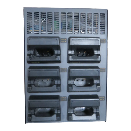
- Page 1 LBI-38706B Operator’s Manual UNIVERSAL MULTI-UNIT CHARGER STANDARD & RAPID WARNING TO PREVENT FIRE OR ELECTRIC SHOCK HAZ- ARD DO NOT EXPOSE THIS PRODUCT TO RAIN OR MOISTURE ericssonz...
-
Page 2: Table Of Contents
Ericsson Inc., at any time and without notice. Such changes will be incorportated into new editions of this manual. No part of this manual may be reproduced or transmitted in any form or by any means, electronic or mechanical, including photo- copying and recording, for any purpose, without the express written permission of Ericsson Inc. -
Page 3: Important Safety Information
(1) the battery charger, (2) the battery, and (3) the product using the battery. CAUTION - To reduce the risk of injury, charge only Ericsson battery packs using the proper battery sleeve. Charging any other battery pack or batteries may cause the battery to burst and cause personal injury or damage. - Page 4 IMPORTANT SAFETY INFORMATION That the wire size is large enough for the AC ampere rating of the charger as specified in Table 1. TABLE 1 RECOMMENDED MINIMUM SIZE FOR EXTENSION CORDS LENGTH OF EXTENSION CORD (ft.) AWG SIZE OF EXTENSION CORD Do not operate charger with damaged cord or plug - replace them im- mediately.
- Page 5 IMPORTANT SAFETY INFORMATION 13. GROUNDING AND AC POWER CORD CONNECTION - To reduce the risk of electrical shock use only a properly grounded outlet. The charger is equipped with an electric cord having an equipment-ground- ing conductor and a grounding plug. Be sure the outlet is properly in- stalled and grounded in accordance with all local codes and ordinances.
- Page 6 IMPORTANT SAFETY INFORMATION Figure 1 - Grounding Methods NOTE Due to the temperature characteristics of nickel-cadmium batteries, the batteries will not accept a full charge at temperature extremes. For maximum capacity, recharge the battery pack at a room temperature of 65°...
-
Page 7: Specifications
SPECIFICATIONS VOLTAGE SOURCE 120 volt switch position 96-144 Vac, 50/60 Hz 230 volt switch position 176-264 Vac, 50/60 Hz POWER CONSUMPTION Rapid Charger 170 watts Standard Charger 30 watts FUSE RATING Rapid Charger F1 - 5 Amp 250 volt Standard Charger F1 - 315 mA, 250 volt F2 - 600 mA, 250 volt RECHARGE TIME... -
Page 8: Description
Voltage Selection switch to the proper source voltage and using the correct power cable (see Accessories and Replacement parts). Battery Pack sleeves are available for the following Ericsson personal ra- dios: RADIO TYPE SLEEVE NUMBER M-PA, M-PD, MTL, PLS, &... -
Page 9: Installation
INSTALLATION The Multi-unit Charger may be located on a desk or other flat surface or mounted on a vertical wall in a convenient location. Ensure either a 120 or 230 Vac 50/60 Hz power source is located near the charger. Check the charger’s voltage selection switch and verify it matches the source voltage. - Page 10 Solid walls - To install the charger on a brick or concrete wall, first insert four wood dowels or fiber, plastic or masonry mounting anchors. Use the following procedure: Using the mounting template provided, locate and mark the charger keyhole mounting points. Drill the holes to match the anchor’s diameter and depth using a carbide drill.
-
Page 11: Indicators
INDICATORS STANDARD MULTI-UNIT CHARGER CHARGE (RED) CONTINUOUS: Indicates battery is charging at the se- lected charging rate... - Page 12 RAPID MULTI-UNIT CHARGER WARNING If both CHARGE and READY indicators are blinking fast, immedi- ately unplug the charger and return it for service. If left in this con- dition, the battery may be severely overcharged causing personal injury or damage.
- Page 13 STAND-BY Both indicators are OFF. Battery not installed. CHARGE (RED) CONTINUOUS: Indicates battery is charging at the se- lected charging rate. BLINKS SLOWLY: Indicates a BATTERY FAULT condition which is preventing an acceptable rapid charge. This condition may result if the battery is too hot or cold, weak or dead, or defective.
-
Page 14: Operation
OPERATION Using The Desk Charger CAUTION For indoor use only. To reduce risk of injury, charge only nickel cad- mium type rechargable batteries. Other types of batteries may explode causing personal injury or damage. Replace defective cords immedi- ately. Plug in the charger and turn it on using the ON/OFF power switch lo- cated in the rear. -
Page 15: Definitions
NOTE On occasion when charging a new battery or a battery which has been out of use for a few months, the charger will prematurely switch to the trickle charge before the battery has been fully charged. If this hap- pens, allow the battery to continue trickle charging overnight. -
Page 16: Troubleshooting Chart
TROUBLESHOOTING CHART CHECK FOR SYMPTOM RED LED indicator Power cable not plugged in does not light. securely. Power switch not turned on. Battery pack not properly installed in charger. Defective charger. Return to a qualified service shop for repair. Charging contacts on the battery or charger are dirty. -
Page 17: Accessories And Replacement Parts
ACCESSORIES AND REPLACEMENT PARTS Accessories and replacement parts may be obtained from your local dealer or by calling the Ericsson Inc. After Market Services 24-Hour Toll Free Number 1-800-368-3277 (USA only) or FAX 1-800- 833-7592. Please provide the description and part number when ordering [e.g. PCS sleeve, 344A3072P6] . - Page 18 Standard Charger Control Board Charger Sleeve F29/4R-A9-0096 See Package Chart STD Charger Power Supply Rapid Charger Power Supply F29/4R-A9-0095 F29/4R-A9-0091 Rapid Charger Constant Current Rapid Charger Control Board F29/4R-A9-0092 F29/4R-A9-0083...
- Page 19 PACKAGE BASE SLEEVE CORD 120V M-PA RAPID 344A3072P8 344A3072P5 344A3072P10 120V M-PA STANDARD 344A3072P9 344A3072P5 344A3072P10 120V PCS RAPID 344A3072P8 344A3072P6 344A3072P10 120V PCS STANDARD 344A3072P9 344A3072P6 344A3072P10 120V M-RK RAPID 344A3072P8 344A3072P7 344A3072P10 120V M-RK STANDARD 344A3072P9 344A3072P7 344A3072P10 230V M-PA RAPID 344A3072P8 344A3072P5...
- Page 20 NOTES...
- Page 21 NOTES...
- Page 22 NOTES...
-
Page 23: Warranty
WARRANTY Ericsson Inc. (hereinafter "Seller") warrants to the original purchaser for use (hereinafter "Buyer") that Equipment manufactured by Seller shall be free from defects in material, workmanship and title, and shall conform to its published specifications. With respect to any Equipment not manufactured by Seller )except for integral parts of Seller’s Equipment to which the warranties set forth above shall apply). - Page 24 Ericsson Inc. Private Radio Systems Mountain View Road Lynchburg,Virginia 24502 1-800-528-7711 Printed in U.S.A.
Need help?
Do you have a question about the 344A3072P1 and is the answer not in the manual?
Questions and answers