Table of Contents
Advertisement
Quick Links
Advertisement
Table of Contents

Summary of Contents for zika MIG-350
-
Page 2: Table Of Contents
CONTENTS 1. Contents ···································································································································· 1 2. Safety warning ···························································································································· 2 3. Machine description ··················································································································· 3 4. Technical parameters table ··········································································································· 4 5. Installation instruction ················································································································· 5 6. Panel function instruction ············································································································· 7 7. Welding parameter recommendation ······························································································ 9 8. Circuit schematic diagram ············································································································ 11 9. -
Page 3: Safety Warning
SAFETY WARNING On the process of welding or cutting, there will be possibility of injury, so please take protection into consideration during operation. For more details please review the Operator Safety Guide, which complies with the preventive requirements of the manufacturer. Electric shock——May lead to death !... -
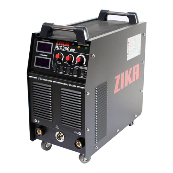
Page 4: Machine Description
MACHINE DESCRIPTION MIG350 CO gas shielded welding machines of our company are inverter welding machines manufactured by our company applying most advanced inversion technology in the world. The development of welding equipment benefits from the appearance of the inverter power supply theory and components. -
Page 5: Technical Parameters Table
TECHNICAL PARAMETERS TABLE Type MIG 350 Item Three-phase Power voltage (V) 380V15% Frequency (Hz) 50/60 Rated input current (A) 21.1 No-load voltage(V) Output current adjustment (A) 50-350 Output voltage (V) 16.5-31.5 Duty cycle (%) Power factor 0.93 Efficiency (%) Type of wire feeder Panasonic interface Wire feed speed (m/min) 3-15... -
Page 6: Installation Instruction
INSTALLATION INSTRUCTION 1) Connect the main circuit cable of the wire feeder to the corresponding output end of the machine, and fasten with bolts. 2) Connect the plug of the control circuit 6-core cable of the wire feeder to the corresponding interface of the machine and lock. - Page 7 Explanatory drawing for Installation of MIG 350: meter Power supply (3Phase ~ 380V) OWNER’S MANUAL - 6 - YF-48N A/0...
-
Page 8: Panel Function Instruction
PANEL FUNCTION INSTRUCTION Change-over switch 1) Ending arc On/Off change-over switch: When in the "Off" position, press the welding gun switch, the welding machine starts working. Now that the welding machine is in the welding state, adjust the output voltage and output current by rotating the welding voltage and welding current turn-knob on the wire feeder. - Page 9 PANEL FUNCTION INSTRUCTION MIG 350 Front Panel Instruction: Current meter Voltage meter Abnormal indicator Power indicator Welding voltage adjustment Arc trait adjustment Welding current adjustment Flux core / sold wire switch Wire diameter selection Gas purge / weld switch Crater on / off switch Negative output terminal Remote control Positive output terminal...
-
Page 10: Welding Parameter Recommendation
WELDING PARAMETER RECOMMENDATION The values listed in the following table are the general specification values under standard condition. ( ) ( ) ( ) ( ) ( ( ) ) ~ ~ ~ ~ ~ ~ ~ ~ ~ ~ ~... - Page 11 ( ) ( ) ( ) ( ) ( ) ( ) ( ) ( ) ( ) ( ) ° ( ) ( ) ° ~ ~ ~ ~ ~ ~ ~ ~ ~ ~ ~ ~ ~ ~ ~...
-
Page 12: Circuit Schematic Diagram
CIRCUIT SCHEMATIC DIAGRAM OWNER’S MANUAL - 11 - YF-48N A/0... -
Page 13: Notes Or Prevention Measures
NOTES OR PREVENTIVE MEASURES 1. Environment 1) The machine can perform in environment where conditions are dry with a dampness level of max 90%. 2) Ambient temperature is between -10 to 40 degrees centigrade. 3) Avoid welding in sunshine or drippings. Do not let water enter the gas 4)... -
Page 14: Questions To Be Run Into During Welding
QUESTIONS TO BE RUN INTO DURING WELDING The phenomenon listed below may be relevant to accessories used, welding material, surroundings and power supply. Pleas improve surroundings and avoid these situations. A. Arc starting difficulty. Arc interruption happens easily: 1) Examine whether grounding wire clamp contacts with the work pieces well. 2) Examine whether each joint has improper contact. -
Page 15: Daily Checking
DAILY CHECKING WARNING! Power supply of distribution box must be cut off prior to maintenance start so as to ensure safety unless there are special requirements. Accidents such as electric shock or burn that may cause serious personal injury may occur because of failing to observe the above-mentioned instructions. - Page 16 DAILY CHECKING WELDING TORCH Position Checking keys Remarks If installation fixed, the front distorted Reason for air hole Nozzle Reason for burning the torch Attach splash or not (can use splash-proof material ) If installation fixed Reason of torch screw thread damage Electric hole Damage of its head and hole blocked or not Reason of unstable arc and broken arc...
- Page 17 DAILY CHECKING WIRE SENDING MACHINE Position Checking keys Remarks Pressing arm If put the arm to the suitable indicating level Lead to unstable arc and wire sending If powder or residue store up in the mouth of the Clean the residue and check the reason tube and solve it Wire diameter and the tube inner diameter match...
-
Page 18: Earlier Checking Diagram For The Abnormal
EARLIER CHECKING DIAGRAM FOR THE ABNORMAL Conclusion of an electric welding machine failure could not determine early even if abnormal phenomenon such as welding unable, arc unstable or bad welding effect occur. The above-mentioned abnormal phenomenon may be caused by some reasons without any failure but the machine operates normally. - Page 19 EARLIER CHECKING DIAGRAM FOR THE ABNORMAL Earlier Checking Diagram For The Abnormal Abnormal Items Area and Item to be Inspected and Maintained 1. Wire feeding wheel does not match with the diameter of wire in texturing tube 2. Crackle on wire feeding wheel, groove blocked up 〇...
-
Page 20: Regular Maintenance
REGULAR MAINTENANCE For abnormal conditions that have been described in “Initial Diagnosis for an Abnormal Phenomenon” and “Abnormal Status Shown by Indicator Lamps and Relevant Treatment Countermeasures”, the reasons should be found out in accordance with the following sequence then the relevant treatment countermeasures should be determined. Failure and Abnormity Examining Power pilot lamp flashes, but the machine does not work. -
Page 21: Troubleshooting And Fault Finding
TROUBLESHOOTING AND FAULT FINDING Notes: The following operations must be performed by qualified electricians with valid certifications. Before maintenance,please contact with us for professional suggestion. MIG 350PRO/400PRO/500PRO/630PRO fault symptom and solution. Fault symptom Solution Power Indicator lamp off Confirm the air switch closed. No running of air fan Power supply available for input cable.
Need help?
Do you have a question about the MIG-350 and is the answer not in the manual?
Questions and answers