Table of Contents
Advertisement
Quick Links
Advertisement
Table of Contents

Related Manuals for Arrel Audio CL-125/4

Summary of Contents for Arrel Audio CL-125/4
- Page 1 CL-125/4 Quad Mic-Line Preamplifier User Manual Issue 0.1...
-
Page 2: Safety Instructions
[Information on Disposal in other Countries outside the European Union] This symbol is only valid in the European Union. If you wish to discard these items, please contact your local authorities or dealer and ask for the correct method of disposal. CL-125/4 User Manual, Issue 0.1 Page 2... -
Page 3: Arrel Audio Contacts
Web: www.arrel-audio.com Support: http://www.arrel-audio.com/support ARREL Audio is continuously working to the improvement of its systems and related documentation. In any case, we reserve the right to change the specifications without notice but in the respect to the current legislation. Disclaimer: The information contained in this manual has been carefully checked and we believed is accurate at the time of publication. -
Page 4: Table Of Contents
ARREL Audio Contacts ......................3 TABLE OF CONTENTS ....................... 4 INTRODUCTION ......................... 5 Housing ..........................5 CL-125/4 Front Panel Controls and Operations ..............6 Input Source selection ...................... 6 Phantom-Power switch ..................... 6 Gain Control knob ......................7 LO-CUT switch ......................... 7 HI-CUT switch ........................ -
Page 5: Introduction
Even if the input stage of the CL-125/4 111 could accept input signals up to +20 dBu, a special protection circuit limits the input level at +12 dBu in order to prevent any damage. -
Page 6: Cl-125/4 Front Panel Controls And Operations
CL-125/4 Front Panel Controls and Operations POWER SWITCH Press the illuminated power-on button to turn on the CL-125/4 (red light on). To turn off press again the power on button (red LED off) (Fig. 1). Fig. 2 CL-125/4 Power on switch INPUT SOURCE SELECTION The CL-125/4 input stage is based on a differential amplifier so it is “electronically... -
Page 7: Gain Control Knob
The output level Indicator is based on a 10-LED Bargraph (7 x green LEDs and 3 x red LEDs) that measures in the range +6/-21 dBu, The resolution in 1.5 dB per step. CL-125/4 User Manual, Issue 0.1 Page 7... -
Page 8: Appendix A: Connections
ARREL Audio APPENDIX A: Connections FIG. 1 CL-125/4 Connections CL-125/4 User Manual, Issue 0.1 Page 8... -
Page 9: Appendix B: Front Panel
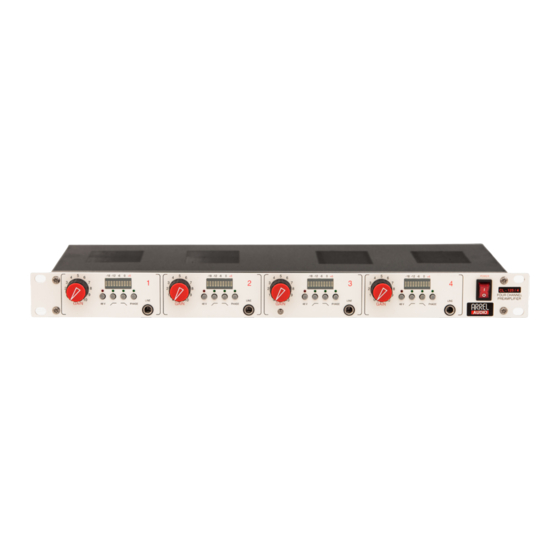
ARREL Audio APPENDIX B: Front Panel FIG. 3 CL-125/4 Front Panel CL-125/4 User Manual, Issue 0.1 Page 9... -
Page 10: Appendix C: Back Panel
ARREL Audio APPENDIX C: Back Panel Fig. 4 CL-125/4 Back Panel CL-125/4 User Manual, Issue 0.1 Page 10... -
Page 11: Technical Specifications
IEC C13 16 A connector, AC mains cord with IEC Schuko 16A Construction 1 U 19" rack mount metal box W 483 mm / 19”, H 44.45 mm/1.75” (1 RU), D 225 mm / 8.86” Dimensions Weight 2.8 kg CL-125/4 User Manual, Issue 0.1 Page 11...
Need help?
Do you have a question about the CL-125/4 and is the answer not in the manual?
Questions and answers