Table of Contents

Subscribe to Our Youtube Channel
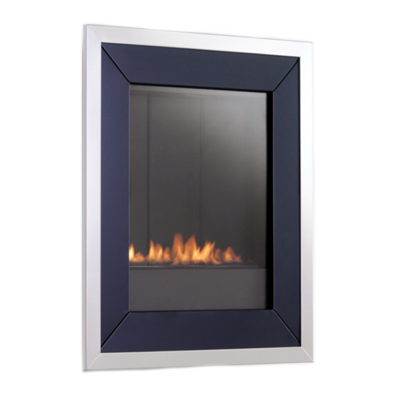
Summary of Contents for Ekofires eko 5010
- Page 1 All instructions must be handed to user for safekeeping Revision A - 06/09 Country(s) of destination - GB/IE eko 5010 eko 5020 eko 5030 eko 5040 fuel effect gas fire manual - remote control - slide control...
- Page 2 Eko 5010 Eko 5020 Eko 5030 Eko 5040 © 2009 Focal Point Fires plc.
- Page 3 Tel: 01202 588 638 Fax: 01202 588 639 www.ekofires.co.uk e-mail: sales@ekofires.co.uk [1] GB - Gas Safe registered operatives (Northern Ireland only- CORGI registered operatives) are the only class of person considered as competent by the HSE under the Gas Safety (Installation and Use) Regulations 1998.
-
Page 4: Table Of Contents
Section Contents Page No. Section Contents Page No. Important Notes Testing and Commisioning Appliance Data Operating the Appliance Installation Requirements Spark Failure 3.1 Room Sizing Setting pressure Site Requirements Fitting the Decorative Frame 4.1 Ventilation Briefing the customer Unpacking the Appliance 10.0 Servicing 5.1 Component Checklist... -
Page 5: Appliance Data
APPLIANCE DATA Gas Group G20 Natural Gas CAT I2H G31 Propane CAT I3P Inlet Pressure (+/-2.0 mbar) 20 mbar 37 mbar Regulator Pressure 25 mbar Max Energy Input Gross 2.0 kW Gross 1.7kW 1.8 kW 1.55 kW Max Gas Rate 0.20 m3/h 0.064 m3/h Min Energy Input... -
Page 6: Ventilation
SITE REQUIREMENTS (continued) Clearances to non-combustibles Non combustible surfaces are defined as brick, metal, marble, concrete etc. and also a number of man-made mate- rials impervious to flame. If in doubt refer to the material manufacturer for further information before proceed- ing with installation. -
Page 7: Unpacking The Appliance
DESCRIPTION Firebox and burner assembly Set of manufacturers instructions Decorative frame assembly (Eko 5010, Eko 5020 and Eko 5030 models) Decorative trim set (Eko 5020 and Eko 5030 models) Glass facia assembly (Eko 5040 models) Spring loaded decorative corner columns (Eko 5040 models) -
Page 8: Fixing The Appliance
FIXING THE APPLIANCE Remove any protective film coatings from the finished/decorative surfaces of the appliance. After having selected the final mounting position of the appliance, taking into account the requirements as specified in sections 3 and 4 of these instructions, the integrity of the wall, and the feasibility of the pro- posed supply pipe routing, the firebox of the appliance may be WARNING... -
Page 9: Testing And Commisioning
TESTING AND COMMISSIONING Turn on and test the gas supply up to the fire for any leaks, in accordance with the current edition of BS 6891 (natural gas installations) or the current edition of BS 5482 pt1 (propane installations). For Republic of Ireland, reference should be made to the current edition of IS813 (the relevant standards governing installation). -
Page 10: Fitting The Decorative Frame
FITTING THE DECORATIVE FRAME ASSEMBLY Eko 5010, Eko 5020 and Eko 5030 Models Eko 5010, Eko 5020 and Eko 5030 Models : Remove the decorative frame assembly from any protective packaging, and remove any protective film that may be present on the frame. -
Page 11: Briefing The Customer
BRIEFING THE CUSTOMER All instructions must be handed to the user for safekeeping. Show the customer how to light and control the fire. After commissioning the appliance, the customer should be instructed on the safe use of the appli- ance and the need for regular servicing. Frequency of service depends on usage, but MUST be carried out at least once annually. -
Page 12: Pilot Assembly
10.2 PILOT ASSEMBLY Clean the pilot assembly with a soft brush and blow through. Check the aeration holes are free of any dirt or lint. Clean thoroughly internally, the connection can be removed from the base of the pilot unit using two spanners to make cleaning easier. -
Page 13: Troubleshooting Guide
11.0 TROUBLESHOOTING GUIDE Fire sparks but pilot does not light • No gas to fire, check isolators are open and gas supply is on. • Pipework blockage, clean out. • Air not fully purged, re purge supply or wait longer. •... -
Page 14: User Instructions
USER INSTRUCTIONS Section Content Page No Important Notes Clearances to Combustibles Ventilation & Room Size Operating Instructions Combustion Monitoring System Cleaning Servicing List of Replacement Parts IMPORTANT NOTES • The installation and Servicing of this fire MUST only be carried out by a competent person in accordance with local Codes and/or Regulations, Building Regulations and the manufacturer's instructions.Failure to comply with the above could lead to prosecution and invalidate the appliance warranty. - Page 15 CLEARANCES TO COMBUSTIBLES - continued Clearances to combustible materials Combustible materials are defined as wood, fabrics, or other materials likely to combust if exposed to flame. Generally, any material, which is likely to discolour, melt or misshape when exposed to moderate heat, should be considered as a combustible material or surface.
- Page 16 COMBUSTION MONITORING SYSTEM This fire is fitted with a combustion monitoring safety device (ODS). If the appliance shuts down during use for no apparent reason then several reasons may be suspected. If a door or window has been opened cre- ating a draught, then pilot disturbance could be the problem and removal of the draught should resolve this.
Need help?
Do you have a question about the eko 5010 and is the answer not in the manual?
Questions and answers