Table of Contents
Advertisement
Quick Links
Advertisement
Table of Contents

Summary of Contents for CNB LXC2050VR
- Page 1 LXC2050VR Network Weatherproof Camera...
- Page 2 Directions Be careful not to cause any physical damage by dropping or throwing LXC2050VR. Especially keep the device out of reach from children. Do not disassemble LXC2050VR. No After Service is assumed when disassembled. Use only the power adapter provided with LXC2050VR.
-
Page 3: Table Of Contents
4.2. Quick Installation Guide ........................14 4.2.1. Connect PC and LXC2050VR to network................. 14 4.2.2. Install IP installer and set IP parameters on LXC2050VR ............15 4.2.3. Remote video connection to LXC2050VR ................18 4.2.4. Additional settings through connection to the Admin Page ............19 Trouble Shooting ........................... -
Page 4: Introduction
LXC2050VR is multi-codec (H.264, MJPEG) IP camera (or network camera) built with embedded software and hardware technology in pancake housing. It enables real time transmission of video of up to 1080P. Remote clients can connect to LXC2050VR for the real time video data through various client solutions running on PC or smart device. -
Page 5: Specification
1.2. Specification Camera Image sensor Progressive scan 1/2.9 inch CMOS 2.0M pixels Full resolution 1,920 x 1,080 pixels (Full HD) Min. illumination 0.2Lux (Color, DSS On), 0.00 Lux (IR LED On) S/N Ratio 50dB or more White Balance Auto Supported Off/ON Lens Built-in Varifocal Lens f=2.8-12mm F1.4... -
Page 6: Applications Of Lxc2050Vr
IP camera, CD (User’s guide, Software…) Optional Items Adapter DC 12V, 2A 1.3. Applications of LXC2050VR Security surveillance (buildings, stores, manufacturing facilities, parking lots, banks, government facilities, military, etc.) Remote monitoring (hospitals, kindergartens, traffic, public areas, etc.) Weather and environmental observation... -
Page 7: Product Description
2. Product Description 2.1. Contents Please make sure that no contents listed below are missing in the package Contents Description Remarks LXC2050VR IP camera LXC2050VR main unit GUIDE PATTERN Guide Pattern Software & User’s Guide Wall Anchors 4EA SCREW 4EA Accessory... -
Page 8: Physical Description
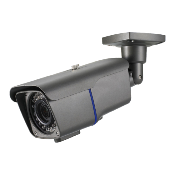
2.3. Physical description Complete System Figure 2-1. External view of LXC2050VR ① MegaPixel Vari-Focal Lens ② IR Illuminator : automatically illuminates depending on the light intensity ③ CDS Sensor ④ Screws (front-4EA & rear-4EA) : Sets the front and back cap ⑤... -
Page 9: Dimension
Figure 2-2. Dimension Rev.1.1 (Sep. 2014) -
Page 10: Inside
Figure 2-3. GASKET ① Video Out : Use this output to monitor the analog video signal while installing. (Select Video Out at menu screen to enable this output) ② Factory Reset Button : Press and hold for more than 5 seconds while power is on to recall factory default settings ③... -
Page 11: Zoom, Focus Lever
TELE ZOOM FOCUS Lever Lever FRONT WIDE NEAR Rev.1.1 (Sep. 2014) -
Page 12: External Connector
Figure 2-5 Power & Network Cable Power : Power input for supplying 12V DC power. Caution : If LXC2050VR is powered by PoE, do not plug in DC Jack with active DC power into DC power connector. Network (LAN) 100Mbps Ethernet connector (RJ-45) with PoE standard (802.3af). -
Page 13: On Site Installation
3. On Site Installation Use cables and conduits that are suitable for the installation. Particular attention should be paid in the installation so that no moisture is allowed to penetrate into the unit through the cables or conduits during the life time of the product. -
Page 14: Getting Started
1. Prepare a PC to run programs for the installation and video connection (PC is needed to assign IP address to LXC2050VR) 2. Connect LXC2050VR as shown in dotted line in Figure 4-1. The DC power through DC adaptor is no need to connect if LAN switch supports PoE (IEEE802.3af). -
Page 15: Install Ip Installer And Set Ip Parameters On Lxc2050Vr
4.2.2. Install IP installer and set IP parameters on LXC2050VR 1. Please insert the Setup CD into your CD-ROM drive, and then please setup Figure 4-2-1. IP Installer Setup 1 2. Please click ‘Install’ button to begin the Installation. Figure 4-2-2. IP Installer Setup 2 3. - Page 16 4. XNET IP Installer program is automatically launched like below right after the program installation. Please double click XNET camera on the list. Figure 4-3. IP Installer Start box 5. Select the camera of which you wish to change the IP address and click (Set IP Address) button to bring up the following box in Figure 4-4.
- Page 17 When you enter the IP address and click Set button, the box shown in Figure 4-4 will appear. Figure 4-5. Select Network Adapter Box 7. Select the adapter and click select button to change the IP address of the camera. Rev.1.1 (Sep.
-
Page 18: Remote Video Connection To Lxc2050Vr
4.2.3. Remote video connection to LXC2050VR 1. Connection through Web Viewer Web Viewer offers simplest way of video connection to LXC2050VR. For video connection, enter the IP address of LXC2050VR in the URL window of Internet Explorer as: Can be omitted the [e.g.] Port 80... -
Page 19: Additional Settings Through Connection To The Admin Page
2. Connection through NVR2 NVR2 is a multi-channel CMS program for to IP camera or Video server. Install NVR2 on remote PC to connect to these products. It is needed to assign connection information to NVR2 program before connection. Details for the NVR2 can be found in [NVR2 User’s Guide]. Figure 4-7. -
Page 20: Trouble Shooting
5. Trouble Shooting 5.1. No power is applied In case of Standard PoE (Power over Ethernet) Power supply through standard PoE is possible only when the following conditions are met. 1. Standard PoE is supported on the product. 2. The LAN switch supports standard PoE. Make sure that both the IP camera and the LAN switch support standard PoE (IEEE 802.3af) ... -
Page 21: Cannot Connect To The Video
5.2. Cannot connect to the Video Check the status of the network connection through PING test. Try the following on your PC : Start > Run > Cmd > Ping IP address (Ex : Ping 172.16.42.51) If “Reply from ~” message is returned (① in the figure below), the network connection is in normal state. -
Page 22: Windows Vista Or Windows 7
5.3. Windows Vista or Windows 7 Windows Vista and Windows 7 users need to configure UAC (User Access Control) and Privilege Level for proper recording and still video capture in NVR2 and Web Viewer. <Windows Vista> 1. UAC (User Access Control) configuration 1) Double-click “User Accounts”... - Page 23 <Windows 7> 1. UAC (User Access Control) configuration 1) Double-click “User Accounts” in control panel 2) Double-click “Change User Account Control setting” 3) Set to “Never notify” Rev.1.1 (Sep. 2014)
- Page 24 2. Privilege Level Control 1) Select “NVR” icon on the desktop 2) Click right mouse button and select “properties” 3) Check “Privilege Level” in “Compatibility” tab Rev.1.1 (Sep. 2014)
-
Page 25: Technical Assistance
5.4. Technical Assistance If you need any technical assistance, please contact your dealer. For immediate service please provide the following information. 1. Model name 2. MAC address and Registration number 3. Purchase date 4. Description of the problem 5. Error message Rev.1.1 (Sep.
Need help?
Do you have a question about the LXC2050VR and is the answer not in the manual?
Questions and answers