
Summary of Contents for AirfoilZ EDGE 540
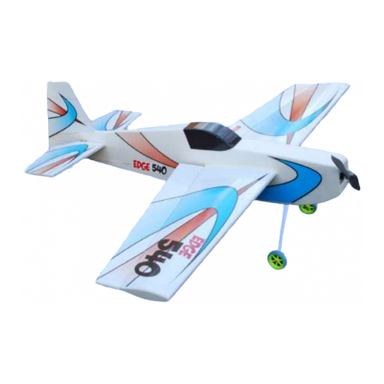
- Page 1 EDGE 540 Full Fuse Assembly Manual Specifications Wing Span: 40 inches Wing Area: 350 in Fuselage Length: 35.6 inches Weight (ready to fly): 19 to 23 oz. Wing Loading: 7.8 to 9.5 oz/ft Designed by Jim Vigani Version 1.0 – 7/31/09...
- Page 2 © Copyright 2009 all rights reserved Limited Warranty AirfoilZ takes pride in the care and attention given to the manufacture of the components in this kit. The company warrants replacement of any materials found to be defective for their intended...
- Page 3 Introduction: Thank you for choosing the AirfoilZ Edge 540 model airplane. We have taken great care to provide a design and kit components that, when properly assembled, will give you a high quality model with outstanding performance. While the assembly is not complicated, the quality and ultimate performance of your model will depend on the care you take while building.
-
Page 4: Kit Contents
Kit Contents: Before you start the assembly of this model, check to make sure that there are no missing parts and that none of the parts have been damaged during shipment. If you have any questions with the assembly or flying of this model, please contact us and we will be happy to assist you. If you need replacement parts please provide the model name. - Page 5 Figure: General Comments on Assembly: While not difficult to assemble, the Edge 540 kit is intended for persons with some building experience. As such, the instructions are presented as a simple sequence that, when followed, will help ensure that the airframe turns out straight and light.
-
Page 6: Fuselage Assembly
Depron foam. Graphics: The Edge 540 comes with printed vinyl graphics. Extra care in cutting out and applying the vinyl panels will result in a painted look for your plane. Some people prefer to lightly mist the surface with “Frebreze” before applying the vinyl. This allows the vinyl to be repositioned while applying them. - Page 7 Skin Assembly Skin Component Parts © Copyright 2009 all rights reserved...
- Page 8 Crutch Assembly Follow the steps in the order outlined below to ensure accurate alignment of the components. © Copyright 2009 all rights reserved...
- Page 9 Step 1 Glue the wing root doubler in place with foam safe CA being careful to ensure the wing openings perfect alignment. Tip: Before joining, apply CA to doubler lightly spray kicker on the fuse skin. Step 2 Using the plywood nose doubler as a guide, glue the top front doubler in place with foam safe CA.
- Page 10 Step 3 Glue the lower rear doubler in place with foam safe CA. NOTE: The lower rear doubler needs to be positioned 3 mm from the edge of the skin. An alignment tab is provided at the rear of the part to ensure proper alignment.
- Page 11 Align the tab on the upper rear double flush with the skin surface. Step 5 Glue the servo supports in place with foam safe CA. Step 6 Trim front doubler alignment tab flush with upper rear doubler. © Copyright 2009 all rights reserved...
- Page 12 Repeat Steps 1 to 3 for the other skin assembly making sure to make a LEFT and a RIGHT side version! Step 7 assemble plywood crutch pieces and check for fit. The pieces should snap together and self align. If the fit is tight, lightly sand the notches for a snug fit.
- Page 13 Landing Gear Mount Assembly Glue the plywood landing gear mount in place with medium CA. Glue the landing gear wire support place with medium CA making sure that the holes in the landing gear mount align with the opening in the landing gear wire support.
- Page 14 Glue the landing gear wire torsion support cap in place with medium CA. Repeat for the other side. Glue crutch bottom support place with medium CA. © Copyright 2009 all rights reserved...
- Page 15 Step 9 Test fit the rudder servo in crutch. Trim opening as necessary to match the servo. Step 10 Test fit the skins on the crutch and check that the slot in the rear of the skin mates with the alignment tab on the rear of the crutch.
- Page 16 Repeat Steps 10 and 11 for the other skin. Step 12 Glue the top rear edges of the fuselage together with medium foam safe CA . Step 13 Test fit the rear top deck and canopy filler pieces and glue in place with medium foam safe CA.
- Page 17 Tip: Before gluing, lightly score the backside of the top skin with an old ballpoint pen where the skin is to be bent around the nose. This prevents without cracking of the foam. Pre-bend the foam before gluing in place. Step 15 Trim the front of the top deck piece and glue in a...
- Page 18 Step 16 Epoxy the motor mount in place making sure it is flush and square with the motor mount support. TIP: Mark the motor mounting hole locations before gluing the motor mount in place. © Copyright 2009 all rights reserved...
- Page 19 Step 17 Glue the bottom cowl skin in place with medium foam safe CA. Tip: Before gluing, lightly score the backside of the bottom skin with an old ballpoint pen to allow the foam to be bent around the nose without cracking. Pre- bend the foam before gluing in place.
- Page 20 Step 20 Glue on the ¼” x ¼” tail post with medium foam safe Step 21 Finish the fuselage construction by sanding the edges smooth. Wing Assembly and Installation Assembling the Spar: © Copyright 2009 all rights reserved...
- Page 21 Step 22 Glue the spar web to the center of the bottom spar cap with thin CA being sure to keep the spar web perpendicular to the spar cap. © Copyright 2009 all rights reserved...
- Page 22 Step 23 Repeat for the top spar cap forming the “I beam” shape. Tip: When completed, lightly sand the spar edges to help it slide into the wing. Wing Assembly: © Copyright 2009 all rights reserved...
- Page 23 Step 24 Place a mark 2” behind the leading edge at each wing tip and at each wing root. Step 25 Glue the 3 mm foam wing alignment tabs in place on the left wing using foam safe CA staying sufficiently away from the spar location mark to allow room for the spar.
- Page 24 Step 26 Mark the center of the spar and test fit it in the wings. Glue the spar into place with Gorilla Glue or 15-minute epoxy. Align the spar with the spar location marks on the wing panels. Step 27 Repeat for the other wing making sure to align the root...
- Page 25 Step 28 Push the wing center joint together making sure the wing root airfoil profile both wings match at the center. Step 29 Carefully sand the wing tip profile and spar end to remove any irregularities. Glue the wing tip caps onto the wing using foam safe CA and foam safe kicker.
- Page 26 Step 30 Trim and sand the wing tip to final shape. Step 31 Cut a ½” diameter hole in the lower wing skin along the wing centerline, just behind the spar for use as an exit for the servo leads. Wing/Fuselage Assembly: ©...
- Page 27 Step 32 Test fit the wing in the fuselage. FORCE! If the fit is tight, sand fuselage opening to fit. Make sure the wing is centered on, square fuselage. With the wing properly aligned, tack glue in place with medium foam safe CA. Step 33 Permanently glue...
- Page 28 Step 34 Using the end of the 3/16” diameter carbon elevator joiner, gently create shallow grove elevator joiner cutout. Step 35 Secure the 3/16” diameter carbon elevator joiner in place with epoxy. Tip: For a lighter joint, a mixture of minute epoxy micro balloons can be...
- Page 29 Step 36 Cut out the foam bridge behind the wood joiner, between the elevator halves. Installing the Horizontal Stabilizer Spar: Step 37 Glue the ¼”x¼” balsa horizontal stabilizer spar rear horizontal stabilizer Assembling and Installing the Horizontal Stabilizer and Elevator: ©...
- Page 30 Step 38 Using sanding block, bevel the leading edge of the elevator as shown allow movement elevator when hinged. Step 39 Temporarily secure the elevator to the stabilizer with tape. Mark the position of the elevator hinges with strips of ”...
- Page 31 Step 40 Cut the tape along the hinge line and remove the elevator. Step 41 Using your Exacto knife, carefully cut a slit along the centerline of both stabilizer elevator at each hinge location. Test fit the hinges into the slits. NOTE: Do not glue the hinges in place at this time.
- Page 32 Step 42 Trim the rear of the horizontal stab slot. SAFE THE PIECE TO GLUE BACK LATER! Step 43 Test fit the stabilizer in the fuselage and check that it fits square to the fuselage and wing. Glue the stabilizer in place with medium foam safe Step 44 Install the elevator and...
-
Page 33: Rudder Installation
Step 44 Glue back the piece of tail post removed in Step 42. Rudder Installation: Step 45 Bevel the leading edge of the rudder and install using the same method as with the other control surfaces. Use 3 hinges. Remember leave approximately ”... -
Page 34: Aileron Installation
Aileron Installation: Step 46 Using the sanding block, bevel the leading edge of the ailerons as shown to allow for movement of the ailerons when hinged. Step 47 Temporarily secure the ailerons to the wing with tape. Mark the position of the aileron hinges with strips ”... - Page 35 Step 48 Cut the tape along the hinge line and remove the ailerons. Using your Exacto knife, carefully slit along centerline of both the aileron wing trailing edge each hinge location and glue the hinges in place NOTE: that the wing has a glue seam along the centerline of the trailing edge.
- Page 36 Step 50 Test fit the servos in the holes. Mark the location plastic servo mounts and remove the servos. Glue the servo mounts in place with foam safe CA. Drill a 1/32 inch diameter pilot hole in the servo mounts each servo mounting lug location.
- Page 37 match distance between the holes in the rudder servo control horn. © Copyright 2009 all rights reserved...
- Page 38 Step 52 Mark the location of the control horns on the control surface and cut a slit in the control surface with an Exacto knife accept control horn mounting tab. © Copyright 2009 all rights reserved...
- Page 39 Step 53 Glue the control horns in place with medium foam safe CA or Epoxy. © Copyright 2009 all rights reserved...
-
Page 40: Landing Gear Installation
Landing Gear Installation: Step 54 Solder a #2 washer on the landing gear. as an inner wheel retainer Tip: Drill a 3/32” hole in a scrap block of wood to use as an alignment tool. Lightly sand the axel washer ensure good bonding of the solder. - Page 41 Step 55 Place a scrap piece of thin plywood cardboard over wheel as a spacer and slide a #2 washer on the axel. Solder in place. Use only enough heat to ensure good solder flow. Excess heat may melt the wheel hub. Completed wheel installation ©...
- Page 42 Step 56 landing gear wires into the slots in the landing gear mount. Tip: Round the corners of the slots so that the wires fit flush to the mount surface. Step 57 Secure the landing gear mount cover in place with screws provided.
- Page 43 Step 58 Tie the wire tailskid to the plywood mount with unwaxed dental floss or thin wire. Secure with CA. Attach the plywood tailskid mount to the rear fuselage using foam safe CA or epoxy. Motor, ESC, Servo, Receiver and Battery installation: Aileron Servo Installation: Step 59 Secure the wing servos...
- Page 44 Step 60 Route the aileron servo leads through the interior of the wing, and out through the exit hole. Step 61 Install the 2-56 threaded rod aileron push rods, securing at both ends with the nylon clevises provided. Bend the rod as appropriate to maintain torsion free geometry.
- Page 45 Elevator Servo Installation: Step 62 Securely glue elevator servo mounts in place with medium foam safe CA. Step 63 Install elevator servo servo mounts outside fuselage. Pre-drill the screw holes with 1/32” drill before installing the screws. Do not over-tighten the screws as strip the screw holes.
- Page 46 Step 64 Install the 2-56 threaded elevator push rod securing at both ends with the nylon clevises provided. Bend the rod as appropriate to maintain torsion free geometry. Rudder Pull-Pull System Installation: Step 65 Cut 1/8” wide exit slots for the pull-pull rudder control wire in the fuselage sides ©...
- Page 47 Step 66 Secure the rudder pull-pull cord on the rudder servo control horn using provided metal sleeves. TIP: Slip the control line through the tubing, then through the control horn, and back through the tube. Squeeze tube with some pliers to flatten it, and then add a drop of thin CA at the end of the tube away from the control horn.
- Page 48 Step 69 Install the lower mid fuse skin over the rudder servo location. TIP: An access hole can be cut for access to the servo horn if desired. Step 70 Mount the motor using #2 wood screws and washers. Check make sure the motor turns freely and there is interference...
- Page 49 Step 71 Mount the ESC with Velcro inside fuselage as shown. Step 72 Mount Receiver with Velcro strips inside the fuselage as shown. © Copyright 2009 all rights reserved...
- Page 50 Step 73 Mount the battery with Velcro strips inside the fuselage shown. Loop a Velcro strap through the slots in the lower crutch to secure the battery in place. Step 73a Velcro strips inside the fuselage on the bottom crutch. ©...
-
Page 51: Preflight Checklist
Step 73b Velcro strip battery. Pre-flight checklist Balancing: We recommend that you perform initial flights with the CG 3 inches behind the leading edge at the wing root. Adjust the CG to get the flight characteristics that suit your taste. 3D flight will improve with a more rearward CG location. - Page 52 © Copyright 2009 all rights reserved...
Need help?
Do you have a question about the EDGE 540 and is the answer not in the manual?
Questions and answers