Table of Contents
Advertisement
Quick Links
Advertisement
Table of Contents

Subscribe to Our Youtube Channel
Related Manuals for Rohde & Schwarz ZN-Z84


Summary of Contents for Rohde & Schwarz ZN-Z84
- Page 1 ® R&S ZN-Z84 Switch Matrix User Manual (=CÄ=2) 1319.5413.02 ─ 02...
- Page 2 ● R&S ® ZN-Z84 "Matrix Base Unit 2x6 Configuration", order no. 1319.4500.02 ● R&S ® ZN-Z84-B22 "Additional Test Ports 7-12 (2 VNA Ports)", order no. 1319.4969.22 ● R&S ® ZN-Z84-B32 "Additional Test Ports 13-18 (2 VNA Ports)", order no. 1319.4969.32 ●...
- Page 3 Basic Safety Instructions Always read through and comply with the following safety instructions! All plants and locations of the Rohde & Schwarz group of companies make every effort to keep the safety standards of our products up to date and to offer our customers the highest possible degree of safety. Our products and the auxiliary equipment they require are designed, built and tested in accordance with the safety standards that apply in each case.
- Page 4 Basic Safety Instructions Symbol Meaning Symbol Meaning Warning! Hot surface Alternating current (AC) Protective conductor terminal Direct/alternating current (DC/AC) Ground Device fully protected by double (reinforced) insulation Ground terminal EU labeling for batteries and accumulators For additional information, see section "Waste disposal/Environmental protection", item 1.
- Page 5 Basic Safety Instructions Operating states and operating positions The product may be operated only under the operating conditions and in the positions specified by the manufacturer, without the product's ventilation being obstructed. If the manufacturer's specifications are not observed, this can result in electric shock, fire and/or serious personal injury or death. Applicable local or national safety regulations and rules for the prevention of accidents must be observed in all work performed.
- Page 6 Basic Safety Instructions 6. The product may be operated only from TN/TT supply networks fuse-protected with max. 16 A (higher fuse only after consulting with the Rohde & Schwarz group of companies). 7. Do not insert the plug into sockets that are dusty or dirty. Insert the plug firmly and all the way into the socket provided for this purpose.
- Page 7 Basic Safety Instructions 2. Before you move or transport the product, read and observe the section titled "Transport". 3. As with all industrially manufactured goods, the use of substances that induce an allergic reaction (allergens) such as nickel cannot be generally excluded. If you develop an allergic reaction (such as a skin rash, frequent sneezing, red eyes or respiratory difficulties) when using a Rohde &...
- Page 8 Basic Safety Instructions 2. Adjustments, replacement of parts, maintenance and repair may be performed only by electrical experts authorized by Rohde & Schwarz. Only original parts may be used for replacing parts relevant to safety (e.g. power switches, power transformers, fuses). A safety test must always be performed after parts relevant to safety have been replaced (visual inspection, protective conductor test, insulation resistance measurement, leakage current measurement, functional test).
- Page 9 Instrucciones de seguridad elementales Waste disposal/Environmental protection 1. Specially marked equipment has a battery or accumulator that must not be disposed of with unsorted municipal waste, but must be collected separately. It may only be disposed of at a suitable collection point or via a Rohde &...
- Page 10 Instrucciones de seguridad elementales Se parte del uso correcto del producto para los fines definidos si el producto es utilizado conforme a las indicaciones de la correspondiente documentación del producto y dentro del margen de rendimiento definido (ver hoja de datos, documentación, informaciones de seguridad que siguen). El uso del producto hace necesarios conocimientos técnicos y ciertos conocimientos del idioma inglés.
- Page 11 Instrucciones de seguridad elementales Símbolo Significado Símbolo Significado Aviso: Cuidado en el manejo de dispositivos Distintivo de la UE para la eliminación por sensibles a la electrostática (ESD) separado de dispositivos eléctricos y electrónicos Más información en la sección "Eliminación/protección del medio ambiente", punto 2.
- Page 12 Instrucciones de seguridad elementales 1. Si no se convino de otra manera, es para los productos Rohde & Schwarz válido lo que sigue: como posición de funcionamiento se define por principio la posición con el suelo de la caja para abajo, modo de protección IP 2X, uso solamente en estancias interiores, utilización hasta 2000 m sobre el nivel del mar, transporte hasta 4500 m sobre el nivel del mar.
- Page 13 Instrucciones de seguridad elementales 6. Solamente está permitido el funcionamiento en redes de alimentación TN/TT aseguradas con fusibles de 16 A como máximo (utilización de fusibles de mayor amperaje solo previa consulta con el grupo de empresas Rohde & Schwarz). 7.
- Page 14 Instrucciones de seguridad elementales Funcionamiento 1. El uso del producto requiere instrucciones especiales y una alta concentración durante el manejo. Debe asegurarse que las personas que manejen el producto estén a la altura de los requerimientos necesarios en cuanto a aptitudes físicas, psíquicas y emocionales, ya que de otra manera no se pueden excluir lesiones o daños de objetos.
- Page 15 Instrucciones de seguridad elementales Reparación y mantenimiento 1. El producto solamente debe ser abierto por personal especializado con autorización para ello. Antes de manipular el producto o abrirlo, es obligatorio desconectarlo de la tensión de alimentación, para evitar toda posibilidad de choque eléctrico. 2.
- Page 16 Instrucciones de seguridad elementales 2. Las asas instaladas en los productos sirven solamente de ayuda para el transporte del producto por personas. Por eso no está permitido utilizar las asas para la sujeción en o sobre medios de transporte como p. ej. grúas, carretillas elevadoras de horquilla, carros etc. Es responsabilidad suya fijar los productos de manera segura a los medios de transporte o elevación.
- Page 17 Quality management Certified Quality System ISO 9001 and environmental Certified Environmental System management ISO 14001 Sehr geehrter Kunde, Dear customer, Cher client, Sie haben sich für den Kauf You have decided to buy a Vous avez choisi d’acheter un eines Rohde & Schwarz Produk- Rohde &...
- Page 18 Customer Support Technical support – where and when you need it For quick, expert help with any Rohde & Schwarz equipment, contact one of our Customer Support Centers. A team of highly qualified engineers provides telephone support and will work with you to find a solution to your query on any aspect of the operation, programming or applications of Rohde &...
-
Page 19: Table Of Contents
® Contents R&S ZN-Z84 Contents 1 Introduction................5 1.1 Option Concept..................5 1.2 About this Manual.................5 2 Putting the Instrument into Operation.........7 2.1 Instrument Tour..................7 2.2 Preparing the Instrument..............11 2.3 Connecting External Devices............18 3 Instrument Functions............21 3.1 Matrix Building Blocks............... 21 3.2 Extensions with 2 Matrix VNA Ports .......... - Page 20 ® Contents R&S ZN-Z84 A.4 Test Tab....................56 A.5 Settings Tab..................57 A.6 System Monitor Tab................60 List of Commands............... 61 Index..................62 User Manual 1319.5413.02 ─ 02...
-
Page 21: Introduction
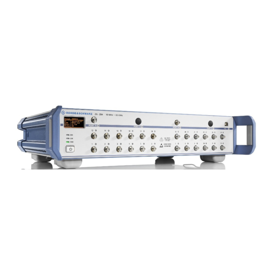
R&S ZN-Z84 Option Concept Introduction The R&S ZN-Z84 is designed as an external switch matrix for the R&S ZNx family of vector network analyzers. Option Concept Depending on the installed options, the R&S ZN-Z84 offers 2 or 4 vector network analyzer (VNA) ports and up to 24 test ports, each of them operating within a fre- quency range of 10 MHz to 8.5 GHz. - Page 22 In addition, it contains notes on pre- ventative maintenance for the R&S ZN-Z84 and on troubleshooting on the basis of the warnings and error messages that the instrument emits. Finally it contains a desription of the ZN-Z8x User tool, which can also be found on the CD-ROM.
-
Page 23: Putting The Instrument Into Operation
Instrument Tour Putting the Instrument into Operation The R&S ZN-Z84 is designed as a base unit (2x6 switch matrix) that can be equipped with up to three optional port extensions. The following description applies to all variants; differences are pointed out explicitly where relevant. - Page 24 Serial: 900033 192.168.1.2 BACK link Direct no link Status The miniature display in the upper left-hand corner of the R&S ZN-Z84 provides the following instrument information: ● Serial number Serial ● IP address IP (see chapter 2.3.2, "LAN", on page 18) ●...
- Page 25 RF stimulus signal and as inputs for the measured RF signals from the DUT (response signals). ● Without port extension the R&S ZN-Z84 base unit offers ports 1 to 6. ● Optional extensions R&S ZN-Z84-B22/B24, -B32/B34 and -B42/B44 add test ports 7 to 12, 13 to 18 and 19 to 24, respectively.
- Page 26 ZN-Z8x User Tool which can be found on the complementary CD. Maximum input levels The maximum input levels specified in the Data Sheet of the R&S ZN-Z84 must not be exceeded. 2.1.1.6 USB Connector Two type B (slave) high speed USB connectors are provided on the R&S ZN-Z84: one at the front panel and one at the back...
-
Page 27: Preparing The Instrument
Micro SD card slot See the R&S ZN-Z84 Data Sheet for interface specification details. Preparing the Instrument This section covers the basic steps to set up the R&S ZN-Z84 and to put it into operation. Safety precautions Be absolutely sure to follow the instructions in the sections below to prevent injury to people or damage to the instrument. - Page 28 ® Putting the Instrument into Operation R&S ZN-Z84 Preparing the Instrument 2.2.1 Unpacking the Instrument The instrument is delivered together with the accessories in a cardboard box. Proceed as follows to unpack its contents: 1. Remove the instrument from its packaging and check the shipment for com- pleteness by comparing it with the shipping document and the accessory lists for the various items.
- Page 29 ® Putting the Instrument into Operation R&S ZN-Z84 Preparing the Instrument Possible damage to the instrument from overheating Restricted air current or excessively high ambient temperatures can cause the instrument to overheat. To ensure sufficient air supply, all fan openings must be clear, and the air- flow at the vents on the sides of the instrument must not be impeded.
- Page 30 ● For the LAN connection, use CAT6 or CAT7 RJ-45 cables (LAN, Ether- net) 2.2.3 Standalone Set Up The R&S ZN-Z84 can be set up on a level surface in a horizontal position or with the feet folded out. User Manual 1319.5413.02 ─ 02...
- Page 31 ® Putting the Instrument into Operation R&S ZN-Z84 Preparing the Instrument Risk of injury when the feet are folded out The feet can retract suddenly if the instrument is moved or if the feet are not completely folded out. This can lead to personal injuries or to damage to the instrument.
- Page 32 ZN-Z84 Preparing the Instrument 2.2.5 Connecting the R&S ZN-Z84 to the AC Power Supply Possible damage to the instrument Before you connect the instrument and turn it on, you must ensure observ- ance of the following points in order to prevent damage to the instrument: ●...
- Page 33 1. Use the supplied power cable to connect the R&S ZN-Z84 to the AC power supply. 2. Switch the power switch to I.
-
Page 34: Connecting External Devices
The R&S ZN-Z84 automatically monitors the most important instrument functions when it is turned on. Connecting External Devices The R&S ZN-Z84 is equipped with different interfaces for establishing a remote control connection, typically from a VNA of the R&SZNx family. 2.3.1 If required, connect the USB connecting cable to the USB type B (slave) port on the rear panel. - Page 35 Connecting External Devices 2.3.2.1 Networks with DHCP The R&S ZN-Z84 is preconfigured to use the dynamic host configuration protocol (DHCP). In such networks, the R&S ZN-Z84 is automatically assigned a free IP address. 2.3.2.2 Static IP Configuration With static IP configuration, the static IP configuration data are usually provided by the network administrator.
- Page 36 ® Putting the Instrument into Operation R&S ZN-Z84 Connecting External Devices User Manual 1319.5413.02 ─ 02...
-
Page 37: Instrument Functions
Matrix Building Blocks Instrument Functions The single function of a switch matrix R&S ZN-Z84 is to dynamically establish RF connections between its VNA ports (statically connected to the RF ports of the VNA) and its test ports (statically connected to the DUT), applying a passive load match to currently unconnected ports. - Page 38 Switch Module 2x6 At the "south" the 2x6 switch modules implement the test ports. At the "north" they are either directly connected to the VNA ports (in R&S ZN-Z84 Base Units without extensions) or to one or two 1x4 switch modules.
- Page 39 ® Instrument Functions R&S ZN-Z84 Matrix Building Blocks 3.1.2 Switch Module 1x4 At the "north" the 2x6 switch modules are connected to the VNA ports. At the "south" they are connected to each of the available 2x6 modules. 1x4 Module SP4T User Manual 1319.5413.02 ─...
-
Page 40: Extensions With 2 Matrix Vna Ports
The 2 matrix VNA ports can be switched to any pair of test ports at the same time ("full crossbar"). 3.2.1 Switch Matrix 2x6 For a R&S ZN-Z84 Base Unit without extension, the switching functionality is pro- vided by a single 2x6 module: 2x6 Module 1 Fig. 3-2: Switch Matrix 2x6... - Page 41 Extensions with 2 Matrix VNA Ports 3.2.2 Switch Matrix 2x12 For test ports 7 to 12 (with option R&S ZN-Z84-B22) a second 2x6 module is installed. To support "full crossbar" switching ● each of the matrix VNA ports is connected to a dedicated 1x4 module ●...
- Page 42 3.2.3 Switch Matrix 2x18 For test ports 13 to 18 (with additional option R&S ZN-Z84-B32) a third 2x6 mod- ule is installed. Again, to support "full crossbar" switching each of the two 1x4 modules is connected to any of the three 2x6 modules:...
- Page 43 Extensions with 2 Matrix VNA Ports 3.2.4 Switch Matrix 2x24 Same extension logic for test ports 19 to 24 (with additional option R&S ZN-Z84- B42) : 2x6 module 4 provides the additional test ports and is connected to both 1x4 modules.
-
Page 44: Extensions With 4 Matrix Vna Ports
● VNA ports B and D with test ports 7-12 and 19-24 (if available) 3.3.1 Switch Matrix 4x12 Option R&S ZN-Z84-B24 adds the two additional physical VNA ports and a sec- ond 2x6 module for test ports 7 to 12 that is directly connected to the VNA ports: 2x6 Module 1 2x6 Module 2 Fig. - Page 45 3.3.2 Switch Matrix 4x18 For test ports 13 to 18 (with additional option R&S ZN-Z84-B34) a third 2x6 mod- ule is installed. This 2x6 module no. 3 is connected to the 1x4 modules of matrix VNA ports A and D:...
- Page 46 Extensions with 4 Matrix VNA Ports 3.3.3 Switch Matrix 4x24 The additional option R&S ZN-Z84-B44 comprises ● 2x6 module no. 4 that provides test ports 19-24 ● two additional 1x4 modules that are connected to VNA ports B and D and to...
-
Page 47: Application
Rohde&Schwarz directly. It is fast and easy to set up and operate a switch matrix via the graphical user interface. For example, a R&S ZNB in combination with a R&S ZN-Z84 can seamlessly work as a multi-port network analyzer with up to 24 ports. -
Page 48: Matrix Setup And Operation At The R&S Znx
RF Connections and Matrix Connectivity Depending on the expansion stage of the R&S ZN-Z84 and the RF connections between VNA and matrix ● certain matrix test ports may not be available for measurements ●... - Page 49 ZN-Z84 RF Connections and Matrix Connectivity Example: Consider a fully equipped R&S ZN-Z84, where the matrix VNA ports of the left submatrix cannot be connected to the test ports of the right submatrix and vice versa. If none of the two VNA ports of a submatrix is connected, obviously no connection between the VNA and the submatrice's test ports can be established and hence neither reflection nor transmission measurements are possible.
-
Page 50: Multiple Paths: Precision Vs. Speed
® Application R&S ZN-Z84 Multiple Paths: Precision vs. Speed R&S ZNx VNA ports Left 2x12 submatrix Right 2x12 submatrix R&S ZN-Z84 full crossbar full crossbar 4x24 Transmission measurement … not possible … possible not possible Fig. 4-2: Partially connected submatrices Multiple Paths: Precision vs. - Page 51 To see the difference between the two optimizations, again consider a DUT with 6 unbalanced ports, connected to a 2-port analyzer via the R&S ZN-Z84 base unit without extension. If all S-parameters shall be measured, at least 6*5/2 succes- sive matrix switching procedures are required (one for each pair of test ports) and the speed optimization would choose one of these minimum solutions.
- Page 52 ® Application R&S ZN-Z84 Multiple Paths: Precision vs. Speed User Manual 1319.5413.02 ─ 02...
-
Page 53: Operation
Basic Information on Remote Control This chapter contains basic information on remote control of the switch matrix R&S ZN-Z84. It contains instructions for setting up the instrument for remote con- trol and a brief description of the status register. 5.1.1 Interfaces and protocols The instrument has different interfaces for remote control. - Page 54 ® Operation R&S ZN-Z84 Basic Information on Remote Control Table 5-1: Remote control interfaces and protocols Interface Comments On the back of the instrument, there is a type B USB interface (slave) for communication with the master device. For details see chapter 5.1.1.2, "USB...
- Page 55 To establish a USB connection, you need ● the vendor ID 0x0AAD (for Rohde & Schwarz) ● the R&S ZN-Z84's product ID 0x011B and ● the instrument's 6-digit serial number (see mini display or label on the back of the instrument)
- Page 56 ® Operation R&S ZN-Z84 Basic Information on Remote Control 5.1.1.3 LAN Interface The instrument is equipped with a LAN interface to enable integration into a local area network (LAN). This interface consists of a connector, a network card, and protocols.
-
Page 57: Remote Control - Commands
Remote Control – Commands This chapter describes all the commands that are relevant for remote control of the switch matrix R&S ZN-Z84. The "List of Commands" at the end of the manual contains all commands in alphabetic order. Tips and tricks for operation ... - Page 58 Usage: Event SYSTem:CLEar Clears the error memory. Usage: Event SYSTem:ERRor? Queries the R&S ZN-Z84 for a list of errors. Return values: <ErrCodes> A list of error numbers (see table below) Usage: Query only Table 5-2: R&S ZN-Z84 Error Codes Error Code...
- Page 59 ® Operation R&S ZN-Z84 Remote Control – Commands Error Code Error String Description ZNZ84_STA- can't read from FPGA regis- TUS_FPGA_ERROR ters ZNZ84_STA- SD card corrupted (selftest TUS_SD_CARD_ERROR failed) ZNZ84_STA- NOR flash corrupted (selftest TUS_NOR_FLASH_ERROR failed) ZNZ84_STATUS_CON- config.ini corrupted (inconsis- FIG_FILE_ERROR tent config.ini file)
- Page 60 ® Operation R&S ZN-Z84 Remote Control – Commands Error Code Error String Description ZNZ84_STA- Internal FPGA voltage of +1.2 TUS_VCC_INT_OUTRANGE V is out of range ZNZ84_STA- AUX. FPGA voltage of +2.5 V TUS_VCC_AUX_OUTRANGE is out of range 5.2.3 Identification ........................44 *IDN? ........................44...
- Page 61 SHOW:LAN:DHCP? ....................46 SET:LAN:DHCP:ON ....................46 SET:LAN:DHCP:OFF ......................46 SET:LAN:GW ....................46 SHOW:LAN:GW? ......................47 SET:LAN:IP ...................... 47 SHOW:LAN:IP? ....................47 SET:LAN:SNMask .....................47 SHOW:LAN:SNMask? ......................48 SET:LAN:INIT SET:LAN:HOST:NAMe <HostName> SHOW:LAN:HOST:NAMe? Queries/sets the hostname of the switch matrix R&S ZN-Z84. User Manual 1319.5413.02 ─ 02...
- Page 62 The LAN hostname string (max. 20 characters). The default hostname is ZNZ84X<serial>. Manual operation: "Hostname" on page 59 SHOW:LAN:MAC:ADDRess? Queries the LAN MAC address of the switch matrix R&S ZN-Z84. Return values: <MACAddress> The LAN MAC address in the format xx-xx-xx-xx-xx-xx, e.g. 00-90-b8-1c-95-b9. Usage:...
- Page 63 ZN-Z84 Remote Control – Commands Setting is only possible with static IP configuration (SET:LAN:DHCP:OFF). Other- wise the R&S ZN-Z84 answers with a "Deactivate DHCP first!" Note that modified LAN settings are not applied until SET:LAN:INIT on page 48 is executed.
- Page 64 ® Operation R&S ZN-Z84 Remote Control – Commands Parameters: <SnMask> The LAN subnet mask in dotted decimal format, e.g. 255.255.255.0. Manual operation: "IP address / Subnet Mask / Standard Gateway" on page 58 SET:LAN:INIT Activates the previously configured LAN settings (DHCP, IP address, subnet mask, default gateway).
- Page 65 ® Operation R&S ZN-Z84 Remote Control – Commands Parameters: <Routes> Non-empty, comma-separated list of routes [A-D][0-24], where each route is determined by a matrix VNA port [A-D] and its connected matrix test port [0-24], for example ROUTe A1,B2 connects matrix VNA Port A with matrix test port 1 and matrix VNA Port B with matrix test port 2.
- Page 66 Remote Control – Commands WRITE:MXINI Writes the current user settings (LAN), to the matrix flash. These settings are loa- ded during instrument startup. Usage: Event Manual operation: "Write all settings to ZN-Z84 (permanent)" on page 59 User Manual 1319.5413.02 ─ 02...
-
Page 67: Maintenance
Packing and storage The storage temperature for the R&S ZN-Z84 is specified in the data sheet. When storing for longer periods, protect the instrument from dust. Prior to transport or shipping, pack the instrument just as it was originally packed. - Page 68 ® Maintenance R&S ZN-Z84 If you no longer have the original packaging, employ a sturdy cardboard box of a suitable size. Ensure that there is enough padding to keep the instrument from slipping around inside the package. Wrap the instrument in anti-static film to pro- tect it against electrostatic charging.
-
Page 69: Azn-Z8X User Tool
® ZN-Z8x User Tool R&S ZN-Z84 Software Installation ZN-Z8x User Tool The "ZN-Z8x User" tool offers the following functions: ● Connect to a R&S ZN-Z8x switch matrix via USB – Select a detected switch matrix – Read its identification parameters (extension type, serial number, firmware version) ●... -
Page 70: Getting Started
2.3.1, "USB", on page 18. When first connected to a particular USB port, the R&S ZN-Z84 is auto-detec- ted by the operating system: Note that the "Generic USB Hub" is only installed if the switch matrix is con- nected via its front USB port (see chapter 2.1.1.6, "USB... -
Page 71: Device Panel
® ZN-Z8x User Tool R&S ZN-Z84 Device Panel Tip: On an R&S ZNx the ZN-Z8x User tool integrates into the "External Tools" softtool of the Vector Network Analyzer GUI (APPLIC hardkey or "System > External Tools" menu). Result The "ZN-Z8x User" tool is started, and automatically connects to the detected switch matrix. -
Page 72: Test Tab
ZN-Z84-<last two digits of highest option>, Serial: <serial number>, Version: <FW version> Remote command: *IDN? Installed Options This line of text lists the options that are installed on a connected R&S ZN-Z84. Remote command: on page 44 *OPT? USB Devices available / Rescan Allows to select one of the detected switch matrices. -
Page 73: Settings Tab
® ZN-Z8x User Tool R&S ZN-Z84 Settings Tab Selecting a matrix in the Device Panel automatically deletes the currently switched routes. Routes / Reset Using the buttons overlaying the RF ports on the picture you can manually create and delete matrix routes. Existing routes are indicated in colors (see "Color VNA... - Page 74 ZN-Z84 Settings Tab IP Setting Select "DHCP" if the R&S ZN-Z84 shall receive its IP configuration via DHCP or "Fixed IP" if the IP configuration shall be assigned manually. Write all settings to ZN-Z84 (permanent) to make the changes persistent.
- Page 75 ® ZN-Z8x User Tool R&S ZN-Z84 Settings Tab Hostname Gets/sets the R&S ZN-Z84's hostname (20 characters). Remote command: SHOW:LAN:HOST:NAMe? SET:LAN:HOST:NAMe Apply LAN Settings (nonpermanent) Activates the (modified) LAN settings on the matrix. Use the Write all settings to ZN-Z84 (permanent) function to make the changes persistent.
-
Page 76: System Monitor Tab
The "System Monitor" tab displays temperatures and voltages at certain refer- ence points. In case of instrument malfunction provide by the requested values to the Rohde&Schwarz service. Use the "Update" button to retrieve the latest monitoring results from the selected R&S ZN-Z84. User Manual 1319.5413.02 ─ 02... -
Page 77: List Of Commands
® List of Commands R&S ZN-Z84 List of Commands *IDN?............................44 *OPT?............................44 *RST.............................42 *SERial?............................45 HANDshake:OFF......................... 41 HANDshake:ON........................... 41 HANDshake?..........................41 ROUTe............................48 SET:LAN:DHCP:OFF........................46 SET:LAN:DHCP:ON........................46 SET:LAN:GW..........................46 SET:LAN:HOST:NAMe........................ 45 SET:LAN:INIT..........................48 SET:LAN:IP..........................47 SET:LAN:SNMask........................47 SHOW:DIRectcon:STATus?......................49 SHOW:LAN:DHCP?........................46 SHOW:LAN:GW?......................... 46 SHOW:LAN:HOST:NAMe?......................45 SHOW:LAN:IP?..........................47... -
Page 78: Index
® Index R&S ZN-Z84 Index Symbols Micro SD ..........11 Mini display ..........8 *IDN ............44 *OPT ............44 *RST ............42 Option *SERial ............ 45 highest ..........44 List ............44 DHCP Networks ........19 Direct Control .......... 11 Power Remote control interface .....37 connector ..........
Need help?
Do you have a question about the ZN-Z84 and is the answer not in the manual?
Questions and answers