Advertisement
Quick Links
Advertisement

Subscribe to Our Youtube Channel
Related Manuals for Interlogix AT1000


Summary of Contents for Interlogix AT1000
- Page 1 AR2000 AT1000 AR2000-R3 AT1000-R3 AT1020 AR2020 AT1020-R3 AR2020-R3 AT1025 AR2025 AT1025-R3 AR2025-R3 AR2010WDMA AR1000 AR2010WDMA-R3 AR1000-R3 AR1030 AR2010WDMB AR1030-R3 AR2010WDMB-R3 IFS Fiber Module Installation & Operation P/N 1062858 • REV B • ISS 01JUL11...
-
Page 2: Audio Input
NOTE: For an unbalanced connection, tie pin 2 to pin 3 and utilize pins 2 and 3 for the audio input to the AT1000 Series module. Utalize pins 1 and 2 for the audio output from the AR1000 Series module. - Page 3 AT1000 FM AUDIO TRANSMITTER OPTICAL OUT International GRD - 6 Fiber AUDIO OUT - 5 Audio Output Systems AUDIO OUT - 4 Incorporated GRD - 3 Balanced AUDIO IN - 2 Audio Input* AUDIO IN - 1 Blue 12 VAC/12 VDC - 3...
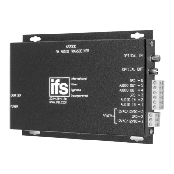
- Page 4 AR2000 AUDIO INPUT Ground Audio Input Audio Input Ground Audio Output AUDIO OUTPUT Audio Output NOTE: For an unbalanced connection, tie pin 2 to pin 3 and utilize pins 1 and 2 for the audio input to the AR2000 Series module. Utalize pins 4 and 5 for the audio output from the AR2000 Series module.
- Page 5 AR2000 FM AUDIO TRANSCEIVER OPTICAL IN OPTICAL OUT International GRD - 6 Fiber AUDIO OUT - 5 Systems Audio Output AUDIO OUT - 4 Incorporated GRD - 3 Balanced AUDIO IN - 2 Audio Input* AUDIO IN - 1 CARRIER Blue 12 VAC/12 VDC - 3 Green...
-
Page 6: Power Led
AT1000 Power LED AR1000/AR2000 Carrier LED Power LED NOTE: WITHOUT PROPER FIBER CONNECTION, LED's DO NOT INDICATE CORRECT OPERATIONAL STATUS OF THE UNIT. - Page 7 AR2000 1 2 3 1 2 3 4 5 6 A Power Connector Audio Connector Optical Out Optical In AT1000 1 2 3 1 2 3 A Power Connector Audio Input Connector C Optical Out AR1000 1 2 3 4 5 6...
- Page 8 PROPER MOUNTING METHOD FOR THE AT/AR2000 1) Locate unit on solid at horizontal or vertical surface. 2) Position unit no closer than 24 inches from any power source or machinery. 3) Securely mount unit using (4) four mounting screws (not provided). 4) Attach power wires to terminal block, black wire to PIN 2 and black wire with white stripe to PIN 1.
-
Page 9: Fcc Compliance
FCC Compliance This device complies with Part 15 of the FCC Rules. Operation is subject to the following two conditions: (1) This device may not cause harmful interference, and (2) this device must accept any interference received, including interference that may cause undesirable operation. Changes or modifications not expressly approved by International Fiber Systems, Inc. - Page 10 Note: Be ready at the equipment before calling. Online Another great resource for assistance with your Interlogix product is our online publication library. To access the library, go to our website at the following location: http://www.interlogix.com/transmission Many Interlogix documents are provided as PDFs (portable document format). To read these documents, you will...
- Page 11 Product Disassembly Instructions for WEEE Per European Directive 2002/95/EC Waste Electrical and Electronic Equipment Required Tools: One number 2 Phillips (crosstip) screwdriver. One number 2 flat screwdriver. For the enclosed box version: 1. Locate and remove box cover securement screws. Usually, but not limited to, at least 4 screws.
- Page 12 Copyright © 2011 UTC Fire & Security. All rights reserved. Trademarks and Interlogix and IFS names and logos are trademarks of patents UTC Fire & Security. Other trade names used in this document may be trademarks or registered trademarks of the manufacturers or vendors of the respective products.
Need help?
Do you have a question about the AT1000 and is the answer not in the manual?
Questions and answers