Table of Contents
Advertisement
Quick Links
OPERATOR'S
MANUAL
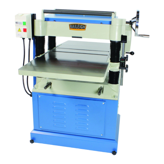
PLANER
MODEL: IP-208
Baileigh Industrial, Inc.
P.O. Box 531
Manitowoc, WI 54221-0531
Phone: 920.684.4990
Fax: 920.684.3944
sales@baileighindustrial.com
REPRODUCTION OF THIS MANUAL IN ANY FORM WITHOUT WRITTEN APPROVAL OF BAILEIGH INDUSTRIAL, INC.
IS PROHIBITED. Baileigh Industrial, Inc. does not assume and hereby disclaims any liability for any damage or loss
caused by an omission or error in this Operator's Manual, resulting from accident, negligence, or other occurence.
Rev. 10/2012
© 2012 Baileigh Industrial, Inc.
Advertisement
Table of Contents

Summary of Contents for Baileigh IP-208
- Page 1 REPRODUCTION OF THIS MANUAL IN ANY FORM WITHOUT WRITTEN APPROVAL OF BAILEIGH INDUSTRIAL, INC. IS PROHIBITED. Baileigh Industrial, Inc. does not assume and hereby disclaims any liability for any damage or loss caused by an omission or error in this Operator’s Manual, resulting from accident, negligence, or other occurence.
-
Page 2: Table Of Contents
Table of Contents THANK YOU & WARRANTY ..................1 INTRODUCTION ......................3 GENERAL NOTES......................3 SAFETY INSTRUCTIONS ....................4 SAFETY PRECAUTIONS ....................6 SPECIFICATIONS ......................9 TECHNICAL SUPPORT ....................9 UNPACKING AND CLEANING ..................10 Cleaning ........................10 INSTALLATION and ASSEMBLY ................. 11 ASSEMBLY EXTENSION TABLE ................. -
Page 3: Thank You & Warranty
THANK YOU & WARRANTY Thank you for your purchase of a machine from Baileigh Industrial. We hope that you find it productive and useful to you for a long time to come. Inspection & Acceptance. Buyer shall inspect all Goods within ten (10) days after receipt thereof. Buyer’s payment shall constitute final acceptance of the Goods and shall act as a waiver of the Buyer’s rights to inspect or... - Page 4 Baileigh Industrial makes every effort to ensure that our posted specifications, images, pricing and product availability are as correct and timely as possible. We apologize for any discrepancies that may occur. Baileigh Industrial reserves the right to make any and all changes deemed necessary in the course of business including but not limited to pricing, product specifications, quantities, and product availability.
-
Page 5: Introduction
After receiving your equipment remove the protective container. Do a complete visual inspection, and if damage is noted, photograph it for insurance claims and contact your carrier at once, requesting inspection. Also contact Baileigh Industrial and inform them of the unexpected occurrence. Temporarily suspend installation. -
Page 6: Safety Instructions
IMPORTANT PLEASE READ THIS OPERATORS MANUAL CAREFULLY It contains important safety information, instructions, and necessary operating procedures. The continual observance of these procedures will help increase your production and extend the life of the equipment. SAFETY INSTRUCTIONS LEARN TO RECOGNIZE SAFETY INFORMATION This is the safety alert symbol. - Page 7 SAVE THESE INSTRUCTIONS. Refer to them often and use them to instruct others. PROTECT EYES Wear safety glasses or suitable eye protection when working on or around machinery. BLADE HAZARD Keep hands and fingers away from the rotating knife blades. These rotating knives can be extremely dangerous if you do not follow proper safety procedures.
-
Page 8: Safety Precautions
HIGH VOLTAGE USE CAUTION IN HIGH VOLTAGE AREAS. DO NOT assume the power to be off. (FOLLOW PROPER LOCKOUT PROCEDURES) SAFETY PRECAUTIONS Wood working can be dangerous if safe and proper operating procedures are not followed. As with all machinery, there are certain hazards involved with the operation of the product. Using the machine with respect and caution will considerably lessen the possibility of personal injury. - Page 9 SAFETY PRECAUTIONS (cont.) 6. Clearing Jams. To avoid serious personal injury from rotating knives, ALWAYS STOP the planer and disconnect power before removing a jammed piece part. Always follow proper lockout/tagout procedures. 7. Using Quality Stock. Inspect the stock over carefully that you intend to plane. NEVER plane a board that has loose knots, staples, or nails in it.
- Page 10 SAFETY PRECAUTIONS (cont.) 22. In-feed Roller Clearance. The in-feed roller is designed to pull material into the rotating cutterhead. To avoid serious personal injury, keep hands, jewelry, clothing, and long hair away from the in-feed roller while operating the machine. 23.
-
Page 11: Specifications
SPECIFICATIONS Cutting Capacity (W x H) 20" x 8" (508 x 203mm) 1/8” (3.1mm) Maximum Depth of Cut 1/4” (6.3mm) Minimum Material Thickness Cutterhead Speed 5000 RPM Number Of Knives 3.25” (82.5mm) Cutter Head Size Motor 5Hp (3.72kw), 1Ph, 60Hz, 220V Shipping Weight (Approx.) 830 lbs. -
Page 12: Unpacking And Cleaning
UNPACKING AND CLEANING Remove planer and stand from the shipping cartons. Check for damage and ensure all parts are intact. Any damage should be reported immediately to your distributor and shipping agent. Before assembling, read the manual thoroughly, familiarizing yourself with correct assembly and maintenance procedures and proper safety precautions. -
Page 13: Installation And Assembly
INSTALLATION and ASSEMBLY WARNING: FOR YOUR OWN SAFETY, DO NOT CONNECT THE MACHINE TO THE POWER SOURCE UNTIL THE MACHINE IS COMPLETELY ASSEMBLED AND YOU READ AND UNDERSTAND THE ENTIRE INSTRUCTION MANUAL. IMPORTANT: Consider the following when looking for a suitable location to place the machine: ... -
Page 14: Assembly Extension Table
ASSEMBLY EXTENSION TABLE WARNING: For your own safety, DO NOT connect the machine to the power source until the machine is completely assembled and you read and understand the entire instruction manual. 1. Use an assistant to help lift and align the holes on the extension table to the main table. -
Page 15: Dust Chute Assembly
DUST CHUTE ASSEMBLY 1. Mount the dust chute to the planer hood with hex head screws & flat washer. 2. Make sure the dust collection system has sufficient capacity and suction for your planer. 3. Always turn on the dust collection system before starting the planer. -
Page 16: Extension Cord Safety
In the event of a malfunction or breakdown, grounding provides a path of least resistance for electric current to reduce the risk of electric shock. This tool is equipped with an electric cord having an equipment-grounding conductor and a grounding plug. The plug must be plugged into a matching outlet that is properly installed and grounded in accordance with all local codes and ordinances. -
Page 17: Electrical Diagram
ELECTRICAL DIAGRAM... -
Page 18: Control The Depth Of Cutting
CONTROL THE DEPTH OF CUTTING CAUTION: Always wear proper eye protection with side shields, face shield, safety footwear, and leather gloves to protect from, chips, dust, burrs, and slivers. The cutting depth scale is a combination of inch / metric scale, the cutting range is from 0 to 8"... -
Page 19: Adjusting Belt Tension
ADJUSTING BELT TENSION Use the two bolts to adjust the belt tension (Fig. 8). When achieved proper position of adjustment tighten bolts to hold in place. Fig. 8 FEED ROLL SPEED RATE The rate of speed is transmitted by shift gears located in gear box. -
Page 20: Roll Transmitting
ROLL TRANSMITTING The purpose of the roll located on top of machine, is transmitting stock after cutting and shaving workpieces. This roll will save you lots of time, and will speed up you’re working rate. (Fig. 11) Fig. 11 CONNECTING DUST COLLECTOR Connect dust collector system to hood of machine, located at the back of machine. -
Page 21: Adjustment Transmitting Roller
ADJUSTMENT TRANSMITTING ROLLER Verify that roller and table are both at the same height. (Fig. 14) Fig. 14 ADJUSTING TABLE ROLLER To reduce friction between stock and table, two table roller have been assembled on machine. Adjustments will be needed when planning with the different types of wood. ... -
Page 22: Constructing Gauge Block
CONSTRUCTING GAUGE BLOCK UNPLUG OR DISCONNECT PLANER FROM POWER SOURCE AND LOCK OUT POWER. The manufacturer has adjusted all machines before delivery. Verify that the screws are properly tightened. The only time you will have to adjust your machine is when it has been functioning for a long time. -
Page 23: Adjusting Cutting Head Parallel To Table
ADJUSTING CUTTING HEAD PARALLEL TO TABLE Cutting Head and Roller Components Infeed Roller Chipbreaker Cutter Head Casting Outfeed Roller Fig. 18 All parallel adjustments have been made to table before shipment, no further adjustments are required. The only verification you should make is to check indirectly the parallel of the cutter head and table. -
Page 24: Adjusting Spring Tension Of Feed Roller
ADJUSTING SPRING TENSION OF FEED ROLLER The infeed roller (A) and the outfeed roller (B) are two of the major parts of automatic transmitting of planer. (Fig. 20). To control pressure, spring tensions are used. Fig. 20 Adjusting Infeed and Outfeed Roller Before starting with the adjustment, you must check the position of the cutting head. -
Page 25: Infeed Roller
WARNING: Knife inserts are dangerously sharp. Use extreme caution when working with or around the knife inserts. 1. UNPLUG OR DISCONNECT PLANER FROM POWER SOURCE AND LOCK OUT POWER. 2. Place gauge block under the cutterhead. 3. Raise the table and rotate the cutter head until the blade just contacts the gauge block. -
Page 26: Check Height Of Pressure Bar
CHECK HEIGHT OF PRESSURE BAR When adjusting pressure bar, the correct position of wooden gauge and 0.2mm thickness gauge must be as shown in (Fig. 21). 1. UNPLUG OR DISCONNECT PLANER FROM POWER SOURCE AND LOCK OUT POWER. 2. Loosen screw (1) and nut (2). Turn the screw to the right so that the pressure bar moves upward. -
Page 27: Digital Readout
DIGITAL READOUT The digital scale equipped with 20” planer can serve many applications, however for wood planning we need only concern ourselves with the ON/OFF, SET, and mm/in buttons. When set properly the digital readout will display the thickness of the finished product. - Page 28 CONVERSION CHART Fraction Decimal Metric 1/32 0.031 0.794 1/16 0.063 1.588 3/32 0.094 2.381 0.125 3.175 5/32 0.156 3.969 3/16 0.188 4.763 7/32 0.219 5.556 0.250 6.350 9/32 0.281 7.144 5/16 0.313 7.938 11/32 0.344 8.731 0.375 9.525 13/32 0.406 10.319 7/16 0.438...
-
Page 29: Maintenance
MAINTENANCE WARNING: Make sure the electrical disconnect is OFF before working on the machine. Maintenance should be performed on a regular basis by qualified personnel. Always follow proper safety precautions when working on or around any machinery. Maintenance on your planer should be done at periodic intervals to ensure that the machine is in good working order. -
Page 30: Parts Lubrication Required
Parts Lubrication Required Position Grease Worm Gear Gear Box Chain Chain Chain Bracket Lead Screw Column Clean & Oil Worm Gear is used to adjust the table up or down. (Fig. 29) The oil in Gear Box must be changed after 2500 hours of work. -
Page 31: Change Lubricant
Change Lubricant When lubrication needs to be changed: 1. Loosen the nut A on the outfeed hole. 2. Clean out old lubrication and let it dry. 3. Tighten nut A 4. Replace clean lubricant by hole B Fig. 32 Fig. 33 Fig. -
Page 32: Parts Diagram - Sheet 1
PARTS DIAGRAM – SHEET 1 To Parts Sheet 2... -
Page 33: Parts Diagram - Sheet 2
PARTS DIAGRAM – SHEET 2... -
Page 34: Parts Diagram - Sheet 3
PARTS DIAGRAM – SHEET 3... -
Page 35: Parts Diagram - Sheet 4
PARTS DIAGRAM – SHEET 4... -
Page 36: Parts List
Parts List Item Descriptions Specification Qty. Belt Guard Front V-Belt Bolt Hex Screw M8 x 1.25P x 20 Flat Washer 8.2 x 30 x 4.0T Hex Screw W/Washer M6 x 1.0P x 12 Belt Guard Rear Hex Nut 5/16"-18NC (12.7B x 6.75H) Cutterhead Pulley Dust Chute Hex Screw... - Page 37 Item Descriptions Specification Qty. Cap Screw M8 x 1.25P x 40 Spring Hook Shaft Cap Screw M6 x 1.0P x 35 Side Cover Guard Magnetic Switch Assembly 5HP, 220V-240V, 1PH (ON/OFF), CSA 42.1 Magnetic Switch 5HP, 220V-240V, 1PH 42.2 Switch Mounting Plate 42.3 Round Hd Screw 3/16"-24NC x 5/8"...
- Page 38 Item Descriptions Specification Qty. 56.8 Retainer Plate ETW-9 Spring Bushing Retainer Plate Spring Washer 8.2 x 15.4mm Pressure Plate Outfeed Roller 5 x 5 x 22mm Chain Sprocket Flat Washer 6.2 x 20 x 3.0T Hex Screw M6 x 1.0P x 16 Bracket Shaft Chip Breaker...
- Page 39 Item Descriptions Specification Qty. Shaft 6 x 6 x 40mm 5 x 5 x 10mm Gear Knob Chain #06B x 50P Chain Sprocket Plug PT1/4"-19 Oil Seal TC28 x 40 x 8 Gearbox Gearbox Gasket Gear Assembly Retaining Ring RTW-32 Shaft Spring Steel Ball...
- Page 40 Item Descriptions Specification Qty. Set Screw M8 x 1.25P x 20 Flat Head Screw M6 x 1.0P x 20 Cover Motor Assembly Flat Washer 13 x 28 x 3.0T Hex Screw M12 x 1.75P x 50 Motor Plate Spacer Motor Assembly 5HP, 220V, 60HZ, 1PH, 2P Hex Nut M12 x 1.75P (19B x 10H)
- Page 41 Item Descriptions Specification Qty. Fixed Bush Main Column Retaining Ring ETW-17 Worm Gear Retaining Ring RTW-38 Bushing 4 x 4 x 10mm Elevating Screw Hex Wrench Hex Wrench Hex Wrench Hex Wrench Wrench Box 8 x 10mm Wrench Box 12 x 14mm Wrench Box 17 x 19mm Roller Bracket...
- Page 42 Item Descriptions Specification Qty. 208.9 Round Hd Screw M4 x 0.7P x 6 208.10 Round Hd Screw M3 x 0.5P x 6 Knob 5/16"-18NC x 3/4" Hex Screw M6 x 1.0P x 12 Hex Head Screw M8 x 1.25P x 30 Wood Screw M6 x 2.6P x 24 Sponge...
- Page 43 NOTES...
- Page 44 , WI 54220 UFEK RIVE ANITOWOC : 920. 684. 4990 F : 920. 684. 3944 HONE BAILEIGHINDUSTRIAL BAILEIGH INDUSTRIAL, INC. 1455 S. C , CA 91761 AMPUS VENUE NTARIO : 920. 684. 4990 F : 920. 684. 3944 HONE BAILEIGH INDUSTRIAL LTD. U...
Need help?
Do you have a question about the IP-208 and is the answer not in the manual?
Questions and answers