Advertisement
Quick Links
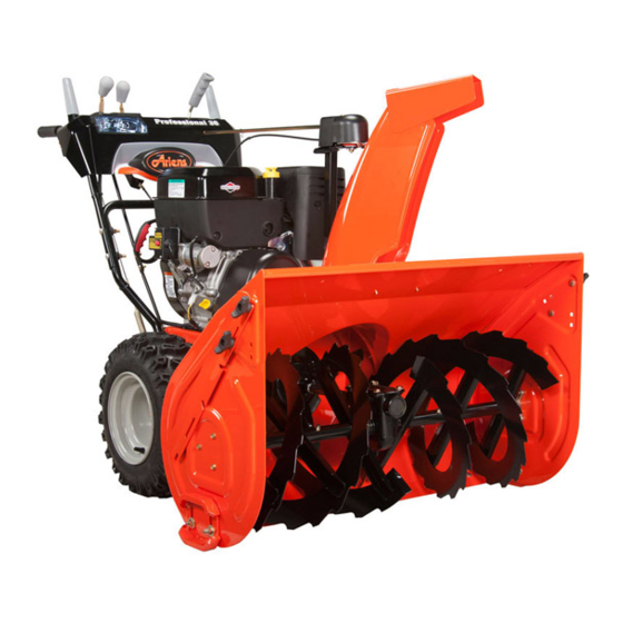
Pro 36 12V (926105 s/n 35000 & up)
•
Step 1: Unfold Handlebar
•
Step 2: Install Discharge Chute
•
Step 3: Install Chute Control Assembly
•
Step 4: Install Discharge Chute Rod
•
Step 5: Install Remote Deflector Cable
•
Step 6: Connect Battery
•
Step 7: Check Function of Dual Handle Interlock
•
Step 8: Check Tire Pressure
•
Step 9: Check Auger Gearcase Oil
•
Step 10: Check Engine Crankcase Oil
•
Step 11: Fill Engine Fuel Tank
•
Step 12: Start Engine
•
Step 13: Stop Engine
READ AND UNDERSTAND ALL INSTRUCTION, WARNING, AND DANGER LABELS.
IMPORTANT: READ OPERATOR'S MANUAL AND ENGINE MANUAL
THOROUGHLY AND FOLLOW THE IMPORTANT SAFE OPERATION PRACTICES
BEFORE OPERATING.
Quick Start Guide
Advertisement

Related Manuals for Ariens Pro 36


Summary of Contents for Ariens Pro 36
- Page 1 Quick Start Guide Pro 36 12V (926105 s/n 35000 & up) • Step 1: Unfold Handlebar • Step 2: Install Discharge Chute • Step 3: Install Chute Control Assembly • Step 4: Install Discharge Chute Rod • Step 5: Install Remote Deflector Cable •...
- Page 2 Step One: Unfold Handlebar Remove the lower and loosen the upper hardware on the handlebar assembly. Loosen the hardware on the shift rod. Put the speed selector lever in the second reverse position. Rotate the handlebar into operating position. IMPORTANT: Be careful not to damage cable spring hooks when rotating handlebar upward.
- Page 3 Step Two: Install Discharge Chute Grease underside of discharge chute ring (if not already greased). Remove mounting hardware from auger housing. Install discharge chute over opening in the auger housing. Finger tighten the mounting hardware removed above. NOTE: Leave discharge chute pedestal loose to help install the chute rod and connect it to the control assembly.
- Page 4 Step Three: Install Chute Control Assembly Remove the rubber grommet from the dash by pinching the long-edged sides together and pulling upward. Set aside for reinstallation. Remove and save the hairpin from the control assembly. Route the chute control assembly underneath the crossbar of the lower handlebar.
- Page 5 Step Four: Install Discharge Chute Rod Remove the gear cover from the gear assembly on the discharge chute by removing the 3/8” screw and lifting upwards. Release the lock teeth on the gear assembly with your finger and rotate the discharge chute 90° left. NOTE: Do not remove the hairpin installed on the chute rod.
- Page 6 Step Four: Install Discharge Chute Rod Cont. IMPORTANT: The hook will prevent the control cable from contacting the engine or muffler guard. NOTE: After the chute rod has been inserted through the hex hole in the control assembly, placing the unit in the service position (see Service Position in Owners Manual) will ease alignment and installation of the hairpin.
- Page 7 Step Five: Install Remote Deflector Control Connect the cable end to the cable anchor on the discharge deflector before clipping the cable to the cable bracket on the discharge chute. Route deflector remote cable along the left side of the chute pedestal.
- Page 8 Step Six: Connect Battery 1. Remove wing nuts from battery cover. 2. Install wire lead to battery terminal. 3. Install battery cover and tighten wing nuts.
- Page 9 Step Seven: Check Function of Dual Handle Interlock Without the engine running, press down (engage) both clutch levers. Release attachment clutch lever. Attachment clutch should remain engaged until traction clutch lever is released, then both clutches must disengage. If they do not, contact your Dealer for repairs.
- Page 10 Step Eight: Check Tire Pressure Check tire pressure and adjust to the pressure listed on tire sidewall.
- Page 11 Step Nine: Check Auger Gearcase Oil Check oil level in auger gearcase (see Check Auger Gearcase in Owners Manual).
- Page 12 Step Ten: Check Engine Crankcase Oil IMPORTANT: The engine is shipped with oil in crankcase. Refer to Engine Manual for detailed instructions.
- Page 13 Step Eleven: Fill Engine Fuel Tank Fill fuel tank. DO NOT OVERFILL! See FILLING FUEL TANK in Owners Manual.
- Page 14 Step Twelve: Starting the Engine...
- Page 15 Starting Engine / Step A: Throttle Move the throttle control lever to the fast position. Operate the engine with the throttle control lever in the fast position.
- Page 16 Starting Engine / Step B: Fuel Valve Turn the fuel shut- off valve to the ON position.
- Page 17 Starting Engine / Step C: Insert the key and turn to the on/start position.
- Page 18 Starting Engine / Step D: Choke Turn the choke control knob to the choke position. NOTE: Choke is usually unnecessary when restarting a warm engine.
- Page 19 Starting Engine / Step E: Prime Push the primer two times. NOTE: Priming is usually unnecessary when restarting a warm engine.
- Page 20 Starting Engine / Step F: (Manual Start) Firmly hold the starter cord handle. Pull the starter cord handle slowly until resistance is felt, then pull rapidly. NOTE: If the engine does not start after repeated attempts, go BRIGGSandSTRATTON.COM or call 1-800-233-3723.
- Page 21 Starting Engine / Step F: (Electric Start) First connect the extension cord to the power cord receptacle and then into a wall receptacle. If an additional extension cord is required, make sure it is a 3-wire.
- Page 22 Starting Engine / Step G: (Electric Start) Depress the push button. After you start the engine, first disconnect the extension cord from the wall receptacle and then from the power cord receptacle.
- Page 23 Starting Engine / Step H: Warm up Allow the engine to warm up for several minutes, Then, slowly move the choke control knob to the run position.
- Page 24 Step Twelve: Stopping the Engine Turn the key to the off position or move throttle control lever to slow and then to the stop position (completely left). Remove the key. Keep away from reach of children. After engine stops, turn the fuel shut-off valve to the closed (vertical) position.
-
Page 25: Additional Resources
Additional Resources • Refer to Owners Manual and Engine Manual • Contact Ariens Company www.ariens.com Phone: 920-756-4688 E-mail: info@ariens.com • For issues concerning engine, please contact Briggs and Stratton www.BRIGGSandSTRATTON.com Phone: 800-233-3723 2011 The Ariens Company. All rights reserved.
Need help?
Do you have a question about the Pro 36 and is the answer not in the manual?
Questions and answers