
Subscribe to Our Youtube Channel
Summary of Contents for Magnetek Flex 8EX A/B
- Page 1 Flex 8EX-A/B System Radio Control Equipment Instruction Manual 0-FLEX-8EXABME-R1 June 2010 © Copyright 2010 Magnetek Material Handling...
- Page 2 Service Information Your New Radio System Thank you for your purchase of Magnetek’s Enrange™ Flex EX radio remote control system. Without a doubt, our Flex EX system is the ultimate solution for providing precise, undeterred, and safe control of your material.
-
Page 3: Table Of Contents
ON/OFF Push Button Function START/AUX Function Magnet ON/OFF Push Button Function Brake Function Momentary Contact Toggled Contact Speed Push Button Function Auxiliary STOP Push Button Function Pitch & Catch Function Flex 8EX A/B System Instruction Manual June 2010 1 of 42... - Page 4 Status Light Indicators & Warnings Transmitter Status Light Indication Receiver Status Light Indication Receiver SQ Light Indication Receiver POWER Light Indication Receiver COM Light Indication Trouble Shooting Tips System Specifications Flex 8EX A/B System Instruction Manual June 2010 2 of 42...
- Page 5 It is the responsibility of the owners, users and operators of the Magnetek Products to know, understand and follow all of these requirements. It is the responsibility of the employer to make its employees aware of all of the above listed requirements and to make certain that all operators are properly trained.
-
Page 6: Introduction
Full compliance – All systems are fully compliant with the FCC Part-15 Rules, European Directives (Safety, EMC, R&TTE, Machinery), and Industry Canada Specifications (IC). Flex 8EX A/B System Instruction Manual June 2010 4 of 42... -
Page 7: Radio Controlled Safety
The following information is intended to be used in conjunction with other rules or regulations already in existence. It is important to read all of the safety information contained in this section before installing or operating the Radio Control System. Flex 8EX A/B System Instruction Manual June 2010 5 of 42... - Page 8 Flex 8EX A/B System Instruction Manual June 2010 6 of 42...
- Page 9 operate any damaged or malfunctioning crane, hoist, lifting device or other material handling equipment Flex 8EX A/B System Instruction Manual June 2010 7 of 42...
- Page 10 TAKEN OUT OF SERVICE AND BE REPORTED TO THE SUPERVISOR. DAMAGED AND INOPERABLE RADIO CONTROLLER EQUIPMENT SHOULD BE RETURNED TO MAGNETEK FOR EVALUATION AND REPAIR. FAILURE TO FOLLOW THIS WARNING COULD RESULT IN SERIOUS INJURY OR DEATH AND DAMAGE TO EQUIPMENT.
- Page 11 Do not attempt to open the battery pack. Do not short circuit the battery. For intrinsically safe environments only use specified Magnetek Telemotive intrinsically safe batteries. Keep the battery pack environment cool during charging operation and storage (i.e., not in direct sunlight or close to a heating source).
- Page 12 Never operate a crane or equipment with two transmitter handsets at the same time unless they are programmed with “Pitch & Catch” function. For information on the “Pitch & Catch” feature, please refer to page 27 and page 38 of this manual. Flex 8EX A/B System Instruction Manual June 2010 10 of 42...
-
Page 13: Transmitter Handset
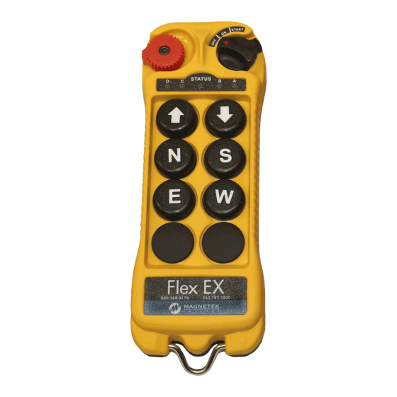
Strap Ring Push Button #4 System Information Push Button #6 System Channel Select A, B, A+B Rotary Switch Crane Number Push Button #1 Battery Cover Push Button #3 FCC Information Flex 8EX A/B System Instruction Manual June 2010 11 of 42... -
Page 14: I-Chip
Internal Illustration (Fig. 03) (Fig. 04) Encoder Board I-CHIP Arial Antenna Function Dip-Switch Transmitting Module Channel Dip-Switch Status LED Display Battery Contact Mechanism Function LED Displays Flex 8EX A/B System Instruction Manual June 2010 12 of 42... -
Page 15: External Illustration
B. RECEIVER UNIT External Illustration (Fig. 05) Shock Mount COM LED Display External Antenna Jack Output Contact Diagram Power LED Display System Information Status LED Display Cord Grip SQ LED Display Flex 8EX A/B System Instruction Manual June 2010 13 of 42... -
Page 16: Internal Illustration
Internal Illustration (Fig. 06) AC Line Filter Decoder Module Power Transformer Output Relay Board Receiving Module Flex 8EX A/B System Instruction Manual June 2010 14 of 42... - Page 17 Top slot → “1” Bottom slot → “0” (Fig. 08) The above dip-switch setting “1 0 0 1 0 0” corresponds to “channel 36” in the system channels table on page 32. Flex 8EX A/B System Instruction Manual June 2010 15 of 42...
-
Page 18: Push Button Functions With Led Displays
LED 1 LED 2 LED 3 * PB5…PB7 → Push button number * Normal → Normal momentary contact * LED 1…LED 4 → Transmitter toggled with designated LED Display Flex 8EX A/B System Instruction Manual June 2010 16 of 42... -
Page 19: Standard Push Button Configuration (A/B Selector)
Normal D/1&2 * PB5…PB7 → Push button number * Normal → Normal momentary contact * A/1&2…D/3&4 → A/B Selector type with designated LED Display (LED 1&2 or LED 3&4) Flex 8EX A/B System Instruction Manual June 2010 17 of 42... - Page 20 LED 1 LED 2 LED 3 * PB5…PB7 → Push button number * Normal → Normal momentary contact * LED 1…LED 4 → Transmitter toggled with designated LED Display Flex 8EX A/B System Instruction Manual June 2010 18 of 42...
-
Page 21: Inline Push Button Configuration (A/B Selector)
Normal D/1&2 * PB5…PB7 → Push button number * Normal → Normal momentary contact * A/1&2…D/3&4 → A/B Selector type with designated LED Display (LED 1&2 or LED 3&4) Flex 8EX A/B System Instruction Manual June 2010 19 of 42... -
Page 22: Channel Change Via Push Buttons
CHANNEL dip-switch. Please note that when channel is set beyond channel 62 via PB1 and PB2 (i.e. channel 63, 68, 88, etc…), the system will recognize it as channel 62. Flex 8EX A/B System Instruction Manual June 2010 20 of 42... - Page 23 (security code function disabled). If you do not remember the 4-digit security code, then you must contact your dealer or distributor for further assistance. Flex 8EX A/B System Instruction Manual June 2010 21 of 42...
- Page 24 2) via an external I-CHIP programmer or duplicator unit available from the factory. Please ask your local dealer for assistance if your system requires serial number/ID code adjustments. (Fig. 11) Flex 8EX A/B System Instruction Manual June 2010 22 of 42...
-
Page 25: System Channel Settings
Top slot → “1” Bottom slot → “0” (Fig. 13) The above dip-switch setting “1 0 0 1 0 0” corresponds to “channel 36” in the system channels table on page 32. Flex 8EX A/B System Instruction Manual June 2010 23 of 42... -
Page 26: Output Relay Configurations
(F/R2) output relays are closed (refer to page 28 on how to set to this function). Forward 1 speed push button pressed Forward 2 speed push button pressed ↓ ↓ F/R2 F/R2 Flex 8EX A/B System Instruction Manual June 2010 24 of 42... -
Page 27: On/Off Push Button Function
ON & OFF rocker switch (refer to page 28 on how to set to this function). When “On” output relay is closed (“On” push button pressed), the “Off” output relay will open automatically, or vice versa. Flex 8EX A/B System Instruction Manual June 2010 25 of 42... -
Page 28: Start/Aux Function
(with “UP” push button still held at 2 speed) will toggle between speed and 3 speed (refer to page 29 on how to set to this function). SPEED Flex 8EX A/B System Instruction Manual June 2010 26 of 42... -
Page 29: Auxiliary Stop Push Button Function
If the first 6 dip-switch positions on the receiving module is set to Ch.01 (“000000” or “000001”), when set to 2-channel scanning (type-3 above), then the receiver will only scan Ch.01 and Ch.02. Flex 8EX A/B System Instruction Manual June 2010 27 of 42... - Page 30 FWD/REV toggled (latched) and affected by the E-stop 0001011 command. 0000111 Safety Magnet On & Off. 0100001 Closed/Closed + Brake. 0100010 Closed/Closed Relay Action + Brake. 0100011 Opened/Closed Relay Action + Brake. Flex 8EX A/B System Instruction Manual June 2010 28 of 42...
- Page 31 Ch.02. Furthermore, you must also set the dip-switch on the receiving module (position #7 & #8) to “10” position (2-channel scanning), please refer to page 23. Flex 8EX A/B System Instruction Manual June 2010 29 of 42...
- Page 32 In-line push button configuration (top to bottom) for Flex 4ES/EX. (Inserted) (Inserted) Program system serial number/ID code and channel from decoder module (Blank) to I-CHIP. Program system serial number/ID code and channel from I-CHIP (Inserted) to decoder module. Flex 8EX A/B System Instruction Manual June 2010 30 of 42...
- Page 33 0.5A (blue) 3.0A (yellow) 2.0A (purple) 2.0A (purple) 1.0A (red) 1.0A (red) 1.0A (red) 0.5A (blue) 3.0A (yellow) 2.0A (purple) 2.0A (purple) * Output relay fuse → 5.0A (clear) Flex 8EX A/B System Instruction Manual June 2010 31 of 42...
- Page 34 Flex 8EX A/B System Instruction Manual June 2010 32 of 42...
- Page 35 111100 433.700MHZ 011101 434.500MHZ 111101 433.725MHZ 011110 434.525MHZ 111110 I-CHIP 433.750MHZ 011111 111111* * When set to all “1” the priority goes to the channel assigned inside the I-CHIP. Flex 8EX A/B System Instruction Manual June 2010 33 of 42...
- Page 36 For F9 and F10 power fuse ratings please refer to page 31. For 12-24VDC power supply, wire #1 corresponds to the negative charge (-) and wire #3 corresponds to the positive charge (+). Wire #2 is for GROUND. Flex 8EX A/B System Instruction Manual June 2010 34 of 42...
- Page 37 The location selected should not be exposed to high levels of electric noise. Mounting the receiver next to an unshielded variable frequency drive may cause minor interference. Always locate the receiver as far away from variable frequency drives as possible. Flex 8EX A/B System Instruction Manual June 2010 35 of 42...
- Page 38 Test the limit switches (if any) to see if they are working properly. If your new remote control is replacing an existing pendant, make sure it is completely disconnected and placed in a safe location to prevent unwanted control commands. Flex 8EX A/B System Instruction Manual June 2010 36 of 42...
- Page 39 “Start” position for up to 2 seconds - this will activate the receiver MAIN (depends on JP3 setting on page 30). Thereafter, the same “Start” position will become an auxiliary function with momentary contact (refer to page 26). Flex 8EX A/B System Instruction Manual June 2010 37 of 42...
- Page 40 Speed push button one time will activate the 3 speed output relay (toggled). If the operator wants 2 speed again, just press the 3 Speed push button one more time. SPEED Flex 8EX A/B System Instruction Manual June 2010 38 of 42...
- Page 41 After changing the batteries make sure that all screws are tightened to avoid water, moisture, dirt, grease, or other liquid penetration. (Fig. 20) ↓ Flex 8EX A/B System Instruction Manual June 2010 39 of 42...
- Page 42 (prior to initiating the START function). Blinking green Push button pressed, signal transmitted. Stop command initiated with receiver Slow red blinks MAIN deactivated. 1 orange blink every 4 seconds Transmitter on standby. Flex 8EX A/B System Instruction Manual June 2010 40 of 42...
- Page 43 Display Type Indication (Red) Power to receiver No power to receiver Receiver COM Light Indication Type Display Type Indication (Red) Power to relay board No power to relay board Flex 8EX A/B System Instruction Manual June 2010 41 of 42...
- Page 44 Outputs do not Check the system wiring again. Please refer to correspond to Incorrect output connection the output contact diagram inside this manual transmitter or on the receiver cover. Flex 8EX A/B System Instruction Manual June 2010 42 of 42...
- Page 45 Transmitter Dimension 184mm (L) x 69mm (W) x 34mm (H) Receiver Dimension 363mm (L) x 228mm (W) x 70mm (H) Transmitter Weight 242g / 8.5oz Receiver Weight 2.5kg / 5.5lb Flex 8EX A/B System Instruction Manual June 2010 43 of 42...
Need help?
Do you have a question about the Flex 8EX A/B and is the answer not in the manual?
Questions and answers