Table of Contents
Advertisement
Quick Links
Advertisement
Table of Contents

Subscribe to Our Youtube Channel
Summary of Contents for SOYO 5XB5
- Page 1 5XB5 82430 TX P54C/P55C PCI Mainboard User’s Guide & Technical Reference...
- Page 2 It is the policy of Soyo Computer Inc. to respect the valid patent rights of third parties and not to infringe upon or assist others to infringe upon such rights.
-
Page 3: Table Of Contents
Table of Contents Chapter 1: Introduction ............ 1 Key Features ................. 1 Unpacking the Mainboard ............. 2 Electrostatic Discharge Precautions..........2 Mainboard Layout w/ Default Settings ......... 3 Chapter 2: Hardware Setup ..........5 Jumpers ..................5 JP5: CMOS Clear Jumper ............5 JP40: CE Test Jumper Pin ............ - Page 4 IDE1/IDE2 Ð On-board Primary/Secondary IDE HDD Connectors ................18 J1 Ð Front Panel Connectors..........18 J17 Ð Keylock & Power LED Connector ......18 J18 Ñ Speaker Connector ............. 18 J19 Ð Hardware Reset Control..........18 PW2 Ñ ATX Power Supply On/Off Switch Connector (Momentary Type)..............
-
Page 5: Chapter 1: Introduction
1 Introduction The 82430 TX PCI mainboard is a high-performance AT form-factor system board that supports P54C/P55C family CPUs and 512K external cache memory on the mainboard. The mainboard is fully compatible with industry standards, and adds many technical enhancements. Key Features ¥... -
Page 6: Unpacking The Mainboard
Introduction Unpacking the Mainboard The mainboard package contains: ¥ The 82430TX Mainboard ¥ This UserÕs Guide ¥ One IDE Bus Master driver diskette Note: Do not unpack the mainboard until you are ready to install it. Follow the precautions below while unpacking the mainboard. 1. -
Page 7: Mainboard Layout W/ Default Settings
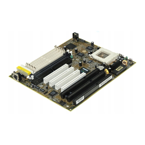
Introduction Mainboard Layout w/ Default Settings Figure 1Ð1. Mainboard Layout 1. ZIF socket 7 (for P54C/P55C) 11. Floppy Connector 2. 82430 TX Chipset 12. IDE1/IDE2 Connector 3. Pipelined Burst SRAM 13. Parallel Port Connector 4. Ultra I/O Chip 14. COM1/COM2 Connector 5. - Page 8 Introduction Default settings are as follows: P54C/P55C 133MHz (P54C) CPU, 512K Pipelined Burst cache, On-board PCI E-IDE Enabled, 2 high speed UARTS Enabled (w/ 16550 FIFO), 1 EPP/ECP port (ECP + EPP mode), 5V DRAM/3.3V DIMM, and AT power supply. PS/2 Conn Mouse...
-
Page 9: Chapter 2: Hardware Setup
2 Hardware Setup This chapter explains how to configure the mainboardÕs hardware. After you install the mainboard, you can set jumpers, install memory on the mainboard, and make case connections. Refer to this chapter whenever you upgrade or reconfigure your system. CAUTION: Turn off power to the mainboard, system chassis, and peripheral devices before performing any work on the... -
Page 10: Jp9: Smart Detect Cpu Voltage Function Auto/Manual Jumper
Hardware Setup JP9: Smart Detect CPU Voltage function Auto/Manual Jumper This jumper is reserved for few old non-Intel CPUs which can not be detected correctly. If you run into problems while detecting the voltage of old non-Intel CPUs, remove this jumper to correct it. JP37: DIMM Voltage Select Jumper Most of DIMMs in the consumer market is still 3.3V and this jumper is reserved only for upgrading purpose in the near feature. -
Page 11: Cpu Type Configuration
Hardware Setup CPU Type Configuration This section shows you how to configure your CPU step by step. Note that you need to check the CPU voltage before installation. This board supports75MHz host bus frequency for Cyrix CPUs. Beware that 75MHz host bus frequency is over the specification of this chipset. Therefore, you hav to use high quality devices to meet the standard of these CPUs, i.e., high quality DRAM and VGA cards. -
Page 12: P54C Ð 100/120/133 Cpu Settings (2.0 X Clock)
Hardware Setup P54C – 100/120/133 CPU Settings (2.0 x clock) Cyrix 6x86/6x86L/6x86MX – PR150 + /PR166 + /PR200 + CPU Settings (2.0 x clock) P54C– 100/50 MHz 82371AB P54C– 120/60 MHz Cyrix 6x86/6x86L – PR150 + /60 MHz P54C– 133/66 MHz Cyrix 6x86/6x86L/6x86MX –... -
Page 13: P54C/P55Cð 150/166 Cpu Settings (2.5 X Clock)
Hardware Setup P54C/P55C– 150/166 CPU Settings (2.5 x clock) Cyrix 6x86MX – PR166/PR200/PR233 CPU Settings (2.5 x clock) AMD K5/K6 – PR150/PR166 CPU Settings (2.5 x clock) P54C/P55C– 150/60 MHz Cyrix 6x86MX – PR166/60 MHz AMD K5 – PR 150/60 MHz 82371AB P54C/P55C–... -
Page 14: P54C/P55C Ð 180/200 Cpu Settings (3.0 X Clock)
Hardware Setup P54C/P55C – 180/200 CPU Settings (3.0 x clock) Cyrix 6x86MX – PR233 CPU Settings (3.0 x clock) AMD K6 – PR200 CPU Setting P54C/P55C– 180/60 MHz 82371AB P54C/P55C– 200/66 MHz AMD-K6/PR200 Cyrix 6x86MX – PR233/66MHz Figure 2Ð1Ð4. CPU Jumper Settings Note: You must equip the CPU with a fan and heat sink for system stability. -
Page 15: P54C/P55C Ð 233 Cpu Settings (3.5 X Clock)
Hardware Setup P54C/P55C – 233 CPU Settings (3.5 x clock) AMD K6 – PR233 CPU Setting 82371AB Socket 7 (586 CPU Family) Figure 2Ð1Ð5. CPU Jumper Settings Note: You must equip the CPU with a fan and heat sink for system stability. -
Page 16: Step 2: Cpu Single/Dual Voltage Setting
Hardware Setup Step 2: CPU Single/Dual Voltage Setting There are two kinds of CPU input voltages due to various designs of CPUsÑsingle voltage and dual voltage. Set your CPU according to the type that you have. For Intel P54C/P55C single and dual voltage series CPUs, there is no need to adjust any jumper for CPU voltag due to the Smart Detect CPU Voltage function. -
Page 17: Dual Voltage Cpu Setting
Hardware Setup Dual Voltage CPU Setting Dual voltage CPUs are designed to use different voltage for VIO and VCore and they include Intel P55C series, Cyrix 6x86L/6x86MX, AMD K6, and MMX technology included CPUs. Refer to the following figures to set these CPUsÕ voltage: 2.8V CPU (default) (i.e., P55C, 6x86L) JP30... -
Page 18: Memory Configuration Table
Hardware Setup Memory Configuration Table SIMM Bank DIMM Bank Bank 0 DIMM 1 DIMM 2 DIMM 3 RAM Type FPM/EDO FPM/EDO FPM/EDO/ FPM/EDO/ SDRAM SDRAM SDRAM Single 4/8/16/32/64 8/16/32/64 8/16/32/64 8/16/32/64 Module Size (MB) Note: Do not install FPM or EDO SIMM/DIMM when you already installed SDRAM type of DIMM. -
Page 19: Multi I/O Port Addresses
Hardware Setup Multi I/O Port Addresses Default settings for multi-I/O port addresses are shown in the table below. Port I/O Address Status LPT1* 378H ECP + EPP COM1 3F8H COM2 2F8H * If default I/O port addresses conflict with other I/O cards (e.g. sound cards or I/O cards), you must adjust one of the I/O addresses to avoid address conflict. -
Page 20: Jp1: Power Supply Selection Jumper
Hardware Setup JP1: Power Supply Selection Jumper This jumper lets you select either the AT or the ATX power supply. Use only one power supply at a time on this mainboard. AT Power Supply (default) ATX Power Supply FDC — FDC Connector Attach floppy cable to this connector. -
Page 21: Kb Conn. Ð Keyboard Connector
Hardware Setup KB Conn. – Keyboard Connector A 5-pin femal DIN keyboard connector is located at the rear of the board. Plug the keyboard jack into this connector. IR1 – IR Connector Attach a 5-pin infrared device cable to this connector for enabling the infrared transfer function. -
Page 22: Usb1Ð Universal Serial Bus Connector
Hardware Setup USB1– Universal Serial Bus Connector Attach 9-pin USB cable to this connector for external USB device. IDE1/IDE2 – On-board Primary/Secondary IDE HDD Connectors Attach cables of hard disk drives to these connectors. J1 – Front Panel Connectors This set of connectors includes: J17 (Keylock/Power LED connector), J18 (Speaker connector), J19 (Reset Connector), PW2 (Momentary Button Connector), and J24 (Turbo/HDD LED Connector). -
Page 23: Pw2 Ñ Atx Power Supply On/Off Switch Connector
Hardware Setup PW2 — ATX Power Supply On/Off Switch Connector (Momentary Type) Attach a two-pin switch to this connector for turning the ATX power supply on/off. J22 – Turbo LED COnnector Attach the turbo LED to J22. The LEd lights when the system is in the Turbo mode. -
Page 24: Chapter 3: Bios Setup
BIOS Setup 3 BIOS Setup The mainboardÕs BIOS setup program is the ROM PCI/ISA BIOS from Award Software Inc. Enter the Award BIOS programÕs Main Menu as follows: 1. Turn on or reboot the system. After a series of diagnostic checks, you are asked to press DEL to enter Setup. -
Page 25: Standard Cmos Setup
BIOS Setup Standard CMOS Setup Run the Standard CMOS Setup as follows. 1. Choose ÒSTANDARD CMOS SETUPÓ from the Main Menu. A screen appears. ROM PCI/ISA BIOS STANDARD CMOS SETUP AWARD SOFTWARE, INC. Date (mm:dd:yy) : Fri, Feb 1 1995 Time (hh:mm:ss) : 7 : 30 : 33 HARD DISKS... - Page 26 BIOS Setup Primary Large Ð Large IDE hard disk (for certain (Secondary) hard disk) Master & Slave Note: If you have any questions on your hard (Continued) disk type or mode, ask your hard disk provider or previous user for details. Drive A &...
-
Page 27: Bios Features Setup
BIOS Setup BIOS Features Setup Run the BIOS Features Setup as follows. 1. Choose ÒBIOS FEATURES SETUPÓ from the Main Menu and a screen with a list of items appears. (The screen below shows the BIOS default settings.) ROM PCI/ISA BIOS BIOS FEATURES SETUP AWARD SOFTWARE, INC. - Page 28 BIOS Setup Boot Sequence Choose the boot device sequence as your need. For example, ÒA, C, SCSIÓ means BIOS will look for an operating system first from drive A, drive C, then SCSI device. Options of this function are: A, C, SCSI C, A, SCSI C, CDÐROM, A CDÐROM, C, A...
- Page 29 BIOS Setup PCI/VGA Enabled: The color of the monitor may be incorrect Palette Snoop if uses with MPEG card. Enable this option to make the monitor normal. Disabled: Disable Snoop function (default). OS Select for OS2 Ð Choosing this when you are using OS/2 DRAM >64MB operation system.
-
Page 30: Chipset Features Setup
BIOS Setup Chipset Features Setup The Chipset Features Setup option changes the values of the chipset registers. These registers control system options in the computer. Note: Change these settings only if you are familiar with the Chipset. Run the Chipset Features Setup as follows. 1. - Page 31 BIOS Setup DRAM Read Burst Use the default setting. (EDO/FP) DRAM Write Burst Use the default setting. Timing Fast EDO Lead Off Use the default setting. Refresh RAS# Assertion Use the default setting. Fast RAS to CAS Delay Use the default setting. DRAM Page Idle Timer Use the default setting.
-
Page 32: Power Management Setup
BIOS Setup Memory Hole At 15M- Choose Enabled or Disabled (default). Some interface cards will map their ROM address to this area. If this occurs, you should select Enabled, otherwise use Disabled. Mem. Drive Str. Default setting is Auto. This item allows (MA/RAS) you to change the setting to adjust the current memory signals. - Page 33 BIOS Setup 1. Choose ÒPOWER MANAGEMENT SETUPÓ from the Main Menu and a screen with a list of items appears. ROM PCI/ISA BIOS CMOS SETUP UTILITY POWER MANAGEMENT SETUP IRQ 8 Break Suspend : Disabled Power Management : Disabled PM Control by APM : Yes ** Reload global Timer Events ** Video Off Method...
- Page 34 BIOS Setup A short description of selected screen items follows: Power Management Options are as follows: User Define Ð LetÕs you define the HDD and system power down times (default). Disable Ð Disables the Green PC Features. Min Saving Ð Doze timer = 1 Hour Standby timer = 1 Hour Suspend timer = 1 Hour HDD Power Down = 15 Min...
- Page 35 BIOS Setup HDD Power Down When the set time has elapsed, the BIOS sends a command to the HDD to power down, which turns off the motor. Time is adjustable from 1 to 15 minutes. The default setting is Disabled. Some older model HDDs may not support this advanced function.
-
Page 36: Pnp/Pci Configuration Setup
BIOS Setup Primary/Secondary Choose Enabled or Disabled (default). IDE 0 Enabled Ð Enables the power management Primary/Secondary timers when Òno activityÓ event is IDE 1 detected. Choose Enabled or Disabled. Floppy Disk/ Serial Port/ Enabled Ð enables the power management Parallel Port timers when Òno activityÓ... - Page 37 BIOS Setup A short description of screen items follows: Resources Manual Ð BIOS doesnÕt manage PCI/ISA PnP Controlled By card (i.e., IRQ) automatically. Auto Ð BIOS auto manage PCI and ISA PnP card (recommended). Reset Disabled Ð Retain PnP configuration data in Configuration BIOS.
-
Page 38: Load Setup Defaults
BIOS Setup Load Setup Defaults This item loads the system values you have previously saved. Choose this item and the following message appears: ÒLoad SETUP Defaults (Y/N)? NÓ To use the SETUP defaults, change the prompt to ÒYÓ and press <Enter>. -
Page 39: Integrated Peripherals
BIOS Setup Integrated Peripherals The Integrated Peripherals option changes the values of the chipset registers. These registers control system options in the computer. Note: Change these settings only if you are familiar with the Chipset. Run the Integrated Peripherals as follows. 1. - Page 40 BIOS Setup IDE Primary Master Choose Auto (default) or Disabled. UDMA/ Auto Ð Supports Ultra DMA mode. IDE Primary Slave UDMA/ IDE Secondary Master UDMA/ IDE Secondary Slave UDMA On-chip Primary PCI Enabled Ð Use the on-board IDE IDE/ (default) On-chip Secondary PCI Disabled Ð...
- Page 41 BIOS Setup Onboard Parallel Port Choose the parallel port I/O address: 378H/IRQ7 (default), 3BCH/IRQ7, 278H/IRQ5, or Disabled to disable this port. Parallel Port Mode Choose ECP+EPP (default), SPP, EPP, or ECP. The mode depends on your external device that connects to this port. ECP Mode Use DMA Choose DMA3 (default) or DMA1.
-
Page 42: Supervisor Password
BIOS Setup Supervisor Password Based on the setting you made in the ÒSecurity OptionÓ of the ÒBIOS FEATURES SETUPÓ, this Main Menu item lets you configure the system so that a password is required every time the system boots or an attempt is made to enter the Setup program. -
Page 43: User Password
BIOS Setup User Password Based on the setting you made in the ÒSecurity OptionÓ of the ÒBIOS FEATURES SETUPÓ, this Main Menu item lets you configure the system so that a password is required every time the system boots or an attempt is made to enter the Setup program. -
Page 44: Ide Hdd Auto Detection
BIOS Setup IDE HDD Auto Detection This Main Menu item automatically detects the hard disk type and configures the STANDARD CMOS SETUP accordingly. This function is only valid for IDE hard disks. Note: ROM PCI/ISA BIOS CMOS SETUP UTILITY AWARD SOFTWARE, INC. HARD DISKS TYPE SIZE... -
Page 45: Appendix: Cpu Setting List
Appendix: CPU Setting List Settings SW1: CPU Frequency Processor Multiplier 1–1 1–2 1–3 1–4 1–5 1–6 Clock AMD K5 50 MHz 1.5X PR75 AMD K5 60 MHz 1.5X PR90 AMD K5 66 MHz 1.5X PR100 AMD K5 60 MHz 1.5X PR120 AMD K5 66 MHz... -
Page 46: Cpu Setting List (Continued)
CPU Setting List (Continued) Settings SW1: CPU Frequency Processor Multiplier 1–1 1–2 1–3 1–4 1–5 1–6 Clock Cyrix MX 75 MHz PR266 Cyrix MX 66 MHz 3.5X PR266 P54C P75 50 MHz 1.5X P54C P90 60 MHz 1.5X P54C P100 66 MHz 1.5X 50 MHz... - Page 47 Note for Memory Configuration On TX chipset motherboards, there is a memory limitation when the system has more than 2 DIMM sockets. The limitations are : Maximum memory size is 256MB total for all RAM socket. DIMM 3 won’t support 64MB or 128MB DIMMs with 64Mbit SDRAM cells. If DIMM 1 and/or DIMM 2 has 64MB or 128MB DIMM’s with 64Mbit SDRAM cells, DIMM 3 must be empty.
Need help?
Do you have a question about the 5XB5 and is the answer not in the manual?
Questions and answers