Advertisement
Quick Links
Advertisement

Related Manuals for National Semiconductor DS10CP154EVK NOPB

Summary of Contents for National Semiconductor DS10CP154EVK NOPB
- Page 1 1.5 Gbps 4x4 LVDS Crosspoint Switch DS10CP154 Evaluation Kit USER MANUAL Part Number: DS10CP154EVK NOPB For the latest documents concerning these products and evaluation kit, visit lvds.national.com. Schematics and gerber files are also available at lvds.national.com. September 2007 Rev. 0.1...
-
Page 2: Table Of Contents
DS10CP154EVK User Manual Table of Contents Table of Contents ........................2 Overview........................... 3 Description..........................4 Evaluation..........................5 Switch Configuration Truth Tables ................... 6 Typical Performance ........................ 7 Page 2 of 7... -
Page 3: Overview
DS10CP154EVK User Manual Overview The DS10CP154EVK is an evaluation kit designed for demonstrating performance of DS10CP154, a 1.5 Gbps 4x4 LVDS Crosspoint Switch. The evaluation kit is comprised of the DS10CP154 with its associated input and output SMA connectors and jumpers to manually configure the switch. -
Page 4: Description
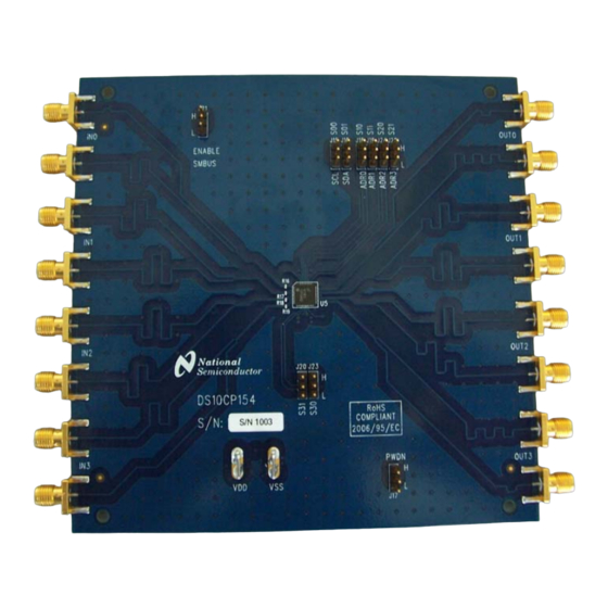
DS10CP154EVK User Manual Description Figure 2 shows the top layer drawing of the PCB with the silkscreen annotations. The 5.25 by 5.25 inch, four-layer PCB is designed to evaluate the functions of the DS10CP154. Figure 2. Top Layer DS10CP154EVK Page 4 of 7... -
Page 5: Evaluation
DS10CP154EVK User Manual Evaluation This section provides recommended test setup procedure for the device evaluation. Figure 3 depicts a typical setup and instrumentation you may use for the device evaluation. 1. Configure the test setup as shown in Figure 3. 2. -
Page 6: Switch Configuration Truth Tables
DS10CP154EVK User Manual Switch Configuration Truth Tables Input Selected Table 1. Input Select Pins Configuration for the Output OUT0 Input Selected Table 2. Input Select Pins Configuration for the Output OUT1 Input Selected Table 3. Input Select Pins Configuration for the Output OUT2 Input Selected Table 4. -
Page 7: Typical Performance
DS10CP154EVK User Manual Typical Performance This section of the User Manual shows a typical eye diagram you can expect to see when evaluating the DS10BR150EVK. Figure 4. DS10CP154 1.5 Gbps NRZ PRBS-7 Output Eye Diagram Page 7 of 7... - Page 13 IMPORTANT NOTICE Texas Instruments Incorporated and its subsidiaries (TI) reserve the right to make corrections, modifications, enhancements, improvements, and other changes to its products and services at any time and to discontinue any product or service without notice. Customers should obtain the latest relevant information before placing orders and should verify that such information is current and complete.
Need help?
Do you have a question about the DS10CP154EVK NOPB and is the answer not in the manual?
Questions and answers