Goldstar MV1502W Service Manual
Hide thumbs
Also See for MV1502W:
- Owner's manual & cooking manual (30 pages) ,
- Installation instructions manual (20 pages)

Related Manuals for Goldstar MV1502W


Summary of Contents for Goldstar MV1502W
- Page 1 Website: http://us.lgservice.com MICROWAVE OVEN SERVICE MANUAL MODEL: MV1502W MV1502B CAUTION BEFORE SERVICING THE UNIT, READ THE SAFETY PRECAUTIONS IN THIS MANUAL. June, 2004 Printed in Korea P/NO : 3828W5S4060...
-
Page 2: Safety Precautions
CAUTION SAFETY PRECAUTIONS PRECAUTIONS TO BE OBSERVED BEFORE AND DURING SERVICING TO AVOID POSSIBLE EXPOSURE TO EXCESSIVE MICROWAVE ENERGY a. Do not operate or allow the oven to be operated with the door open. b. Make the following safety checks on all ovens to be serviced before activating the magnetron or other microwave source, and make repairs as necessary;... -
Page 3: Table Of Contents
FOREWORD Read this Manual carefully. Failure to adhere to or observe the information in this Manual may result in exposing yourself to the Microwave Energy normally contained within the oven cavity. TABLE OF CONTENTS (Page) SAFETY PRECAUTIONS - - - - - - - - - - - - - - - - - - - - - - - - - - - - - - - - - - - - - - - - - - - - - - - - - - - - - - - - - - - - - - - - - - - - - - - - - - - - - - - - - - - - - - - - - - - - - - - - - - - - Inside front page SPECIFICATIONS - - - - - - - - - - - - - - - - - - - - - - - - - - - - - - - - - - - - - - - - - - - - - - - - - - - - - - - - - - - - - - - - - - - - - - - - - - - - - - - - - - - - - - - - - - - - - - - - - - - - - - - - - - - - - - - - - - - - - - - - - - - - - - - - 1-1 CAUTIONS - - - - - - - - - - - - - - - - - - - - - - - - - - - - - - - - - - - - - - - - - - - - - - - - - - - - - - - - - - - - - - - - - - - - - - - - - - - - - - - - - - - - - - - - - - - - - - - - - - - - - - - - - - - - - - - - - - - - - - - - - - - - - - - - - - - - - - - - - - 2-1 INSTALLATIONS - - - - - - - - - - - - - - - - - - - - - - - - - - - - - - - - - - - - - - - - - - - - - - - - - - - - - - - - - - - - - - - - - - - - - - - - - - - - - - - - - - - - - - - - - - - - - - - - - - - - - - - - - - - - - - - - - - - - - - - - - - - - - - - - - - 3-1... -
Page 4: Specifications
SPECIFICATIONS Rated Power Consumption - - - - - - - - - - - - - - - - - - - - - - - - - - - - - - - - - - 1,500W maximum (Microwave oven+Cook top lamp+Ventilation fan) Microwave Output - - - - - - - - - - - - - - - - - - - - - - - - - - - - - - - - - - - - - - - - - - - - - - - 1,000W (IEC 60705) Adjustable 100W through 1000W, 10 steps Frequency - - - - - - - - - - - - - - - - - - - - - - - - - - - - - - - - - - - - - - - - - - - - - - - - - - - - - - - - - 2,450 MHz ±... -
Page 5: Cautions
CAUTIONS Unlike other appliances, the microwave oven is MICROWAVE RADIATION high-voltage and high-current equipment. Personnel should not be exposed to the Though it is free from danger in ordinary use, microwave energy which may radiate from the extreme care should be taken during repair. magnetron or other microwave generating device if it is improperly used or connection. -
Page 6: Installations
INSTALLATIONS BEFORE YOU BEGIN, READ THE FOLLOWING INSTRUCTIONS COMPLETELY AND CAREFULLY. PRECAUTIONS ON INSTALLATION A. Plug the power supply cord into a 120V AC, 60Hz, single-phase power source with a capacity of 15A or 20A. B. Avoid placing the unit in a location where there is direct heat or splashing water. -
Page 7: Operating Instructions
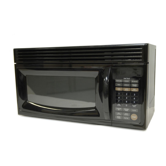
OPERATING INSTRUCTIONS CONTROL PANEL... -
Page 8: Control Panel Instructions
CONTROL PANEL INSTRUCTIONS 1. Display: The Display includes a clock and indicators 11. Number: Touch number pads to enter cooking to tell you time of day, cooking time settings and time, power level, quantities or weights. cooking functions selected. 12. TIME COOK: Touch this pad to set a cooking time. 2. -
Page 9: Overall Circuit Diagram
OVERALL CIRCUIT DIAGRAM SCHEMATIC DIAGRAM... -
Page 10: Matrix Circuit For Touch Key Board
MATRIX CIRCUIT FOR TOUCH KEY BOARD AUTO TIME COOK COOK AUTO AUTO CUSTOM DEFROST REHEAT KITCHEN CLOCK Ez On TIMER TIME POWER DEFROST LEVEL STOP CLEAR... -
Page 11: General Information For Service
GENERAL INFORMATION FOR SERVICE GENERAL PRECAUTIONS IN USE FEATURES AND SPECIFICATIONS FEATURES A. Never operate the unit when it is empty. Operating the oven with no load may shorten the A. The safety systems incorporated in this model are: life of the magnetron. Whenever cooking dry foods (1) Primary interlock switch (dried fish, bread, etc.) or a small amount of food, (2) Secondary interlock switch... -
Page 12: Service Information
SERVICE INFORMATION PRECAUTIONS AND REPAIR SERVICE TIPS PRELIMINARY (3) Do not operate the unit until it is completely A. SINCE NEARLY 2,100 VOLTS EXISTS IN SOME repaired, if any of the following conditions exist. CIRCUITS OF THIS UNIT REPAIRS SHOULD BE The unit must not be operated. -
Page 13: Microwave Leakage Test
MICROWAVE LEAKAGE TEST CAUTIONS MEASURING MICROWAVE ENERGY LEAKAGE • Be sure to check microwave leakage prior to servicing the oven if the oven is operative prior to • Pour 275±15cc of 20±5°C(68±9°F) water in a beaker servicing. which is graduated to 600 cc, and place the beaker •... -
Page 14: Power Output Measurement
MEASUREMENT WITH THE OUTER CASE NOTE WHEN MEASURING REMOVED (1) Do not exceed meter full scale deflection. (2) The test probe must be removed no faster than (1) When you replace the magnetron, measure for 1 inch/sec (2.5cm/sec) along the shaded area, microwave energy leakage before the outer case otherwise a false reading may result. -
Page 15: Disassembly Instructions
DISASSEMBLY INSTRUCTIONS IMPORTANT NOTES: (4) Remove 2 screws securing the circuit board. UNIT MUST BE DISCONNECTED FROM ELECTRICAL OUTLET WHEN MAKING REPAIRS, RE-PLACEMENTS, ADJUSTMENTS AND CONTIN- UITY CHECKS. WAIT AT LEAST ONE MINUTE, UNTIL THE HIGH VOLTAGE CAPACITOR IN THE HIGH VOLTAGE POWER SUPPLY HAS FULLY DISCHARGED. - Page 16 HOW TO REMOVE THE F.P.C. CONNECTOR HOW TO INSERT THE F.P.C. CONNECTOR Follow the steps below as illustrated in Figures 4 Follow the steps below as illustrated in Figures 6 and 5 to remove the F.P.C. connector. and 7 to insert the F.P.C. connector. (1) Hold the edges of the plastic fastener with (1) Insert the F.P.C.
- Page 17 B. REMOVING THE OUT CASE(Figure 8) (6) Remove the power cord cover from outcase by (1) Remove the vent grille by removing two screws removing a screw. securing it to the out case. (7) Remove the power cord to the inner of the out (2) Remove two screws securing it to the front bracket.
- Page 18 C. REMOVING THE DOOR INTERLOCK SWITCHES (Figures 9,10) (1) Disconnect the wire leads from the interlock switches. (2) Remove two screws securing the Latch Board. (3) Make necessary replacements and check microwave energy leakage according to “ADJUSTMENT PROCEDURE” on page 7-12. Latch Board Secondary Interlock Switch...
- Page 19 D. REMOVING MAGNETRON NOTE: • When removing the magnetron, make sure that its (Figures 11 Through 13) dome does not hit any adjacent parts, or it may be (1) Remove vertgrille. damaged. (2) Remove mount, all. • When replacing the magnetron, be sure to install the (3) Remove outcase.
- Page 20 E. REMOVING DOOR (Figure 14) (1) Remove the vent grille by two screws securing it to the outcase loosening. (2) Lift up and push the door. NOTES: • After replacing the door, be sure to check that the primary interlock switch, the secondary interlock switch and the interlock monitor switch is in good operating normally.
- Page 21 G. ASSEMBLING DOOR (3) Carefully pull the ventilation motor ASS'Y out of the (1) When mounting the door assembly to the oven microwave oven. (See Figure 18) assembly, be sure to adjust the door assembly parallel to the chassis. Also adjust so the door has no play between the inner door surface and oven frame assembly.
- Page 22 I. REMOVING THE TURNTABLE MOTOR (1) Remove the turntable. (2) Remove the turntable shaft VERY CAREFULLY with a slotted screwdriver. (Figure 19) (3) Remove the base plate by removing 6 screws securing it to the oven cavity. (Figure 20) (4) Disconnect the leadwire from the turntable motor terminals.
-
Page 23: Interlock System
INTERLOCK SYSTEM INTERLOCK MECHANISM The door lock mechanism is a device which has been specially designed to eliminate completely microwave activity when the door is opened during cooking and thus to prevent the danger resulting from the microwave leakage. ADJUSTMENT PROCEDURES CHECK THE DOOR LATCH AND SWITCH CLOSING. - Page 24 TEST THE LATCH AND SWITCH SEQUENCE (5) Open the oven door slowly. Watch the door latch, (7) When you achieve the proper sequence of the Secondary Switch. Release Rod and Lever on switches in Steps 5 and 6, tighten the latch board the switches to make sure they are zero to the screws at that point.
-
Page 25: Interlock Continuity Test
INTERLOCK CONTINUITY TEST A. PRIMARY INTERLOCK SWITCH TEST B. SECONDARY INTERLOCK SWITCH TEST When the door is opened slowly, an audible click Disconnect the wire lead from the secondary should be heard at the same time or successively switch. at intervals and the latches should activate the Connect the ohmmeter leads to the common switches with an audible click. -
Page 26: Test And Checkout Procedures And Trouble Shooting
TEST AND CHECKOUT PROCEDURES, AND TROUBLE SHOOTING - CAUTIONS - Filament - DISCONNECT THE POWER SUPPLY CORD FROM Winding THE WALL OUTLET WHENEVER REMOVINGING THE CABINET FROM THE UNIT. PROCEED WITH THE TESTS ONLY AFTER Secondary DISCHARGING THE HIGH VOLTAGE CAPACITOR Winding AND REMOVING THE WIRE LEADS FROM THE PRIMARY WINDING OF THE HIGH VOLTAGE... - Page 27 COMPONENTS TEST PROCEDURES RESULTS Measure the resistance: (1) Terminal to terminal Normal reading: Momentarily indicates several ohms, and then gradually returns to infinite ohms. Abnormal reading: Indicates continuity or infinite ohms Ohm- from the beginning. meter HIGH-VOLTAGE Figure 25-a CAPACITOR (2) Terminal to case Normal readings: Infinite.
- Page 28 COMPONENTS TEST PROCEDURES RESULTS Measure the resistance between terminal When When not pins of connector KEY CONNECTOR. touched touched Resistance NOTE: value When reconnecting the FPC connector, Less than More than make sure that the holes on the FPC 400 ohms 1 mega ohm connector are properly engaged with hooks on the plastic fastener.
-
Page 29: Checkout Procedures
COMPONENTS TEST PROCEDURES RESULTS POWER Check for continuity of relay 2 with an LEVEL ohm-meter. (Remove wire leads from relay 2 and 4 sec 18 sec operate the unit.) 6 sec 16 sec Relay 7 8 sec 14 sec 10 sec 12 sec 12 sec 10 sec... - Page 30 (2) CHECKOUT PROCEDURES FOR RELAY. - PROBLEM (A) - TT motor and oven lamp turn on without touching START key when the door is closed. Remove the mate connector of I/O GOOD CON from the circuit board. Does the unit still operate? Replace the Defective circuit board...
- Page 31 (3) CHECKOUT PROCEDURES FOR CIRCUIT BOARD The following symptoms indicate a defective circuit 6) Wrong figures appear. board. 7) The figures of all digits. 1) The start function fails to operate but the high 8) Some of the indicators do no flicker light up. voltage Systems, the interlock switches, the door 9) The clock does not keep time properly.
- Page 32 7-21...
- Page 33 7-22...
- Page 34 7-23...
- Page 35 7-24...
-
Page 36: Exploded View
EXPLODED VIEW DOOR PARTS 13552A 13581A 13536A 13213A 13720D WTT028 14890A 14026A 14970A 13650A... - Page 37 CONTROLLER PARTS 268711 24781M 24810P WTP018 23572A WTT029 23506A...
- Page 38 OVEN CAVITY PARTS WTT021 34960A WTT028 WTT027 WTT029 33530A WTT029 For model MV1502A 34810Q WTT027 For model MV1502B 33112U 368771 56804A 33550L 63303A 63302A 36912C 34890C 34810T WTT022 WTT022 35230A...
- Page 39 LATCH BOARD PARTS 43500A 466001 WSZ084 43501A 466003 466001 44510A...
- Page 40 INTERIOR PARTS (I) WSZ002 33390G 34370T 56324A WTT021 35889A 56170D 33052A 33740A WTT021 36549S WSZ002 WTP013 53300B 56851D WSZ002 54810C 50CZZH 53300A...
- Page 41 INTERIOR PARTS (II) 56912B 55231C 36549V 53550L 56804A WTT028 56411A 55262A 50FZZA 56930V 55006F 568771 WSZ002...
- Page 42 INSTALLATION PARTS 63300M 65862D 65862B 63861A VINYL...
Need help?
Do you have a question about the MV1502W and is the answer not in the manual?
Questions and answers