
Subscribe to Our Youtube Channel
Related Manuals for Salter Brecknell LPS-150

Summary of Contents for Salter Brecknell LPS-150
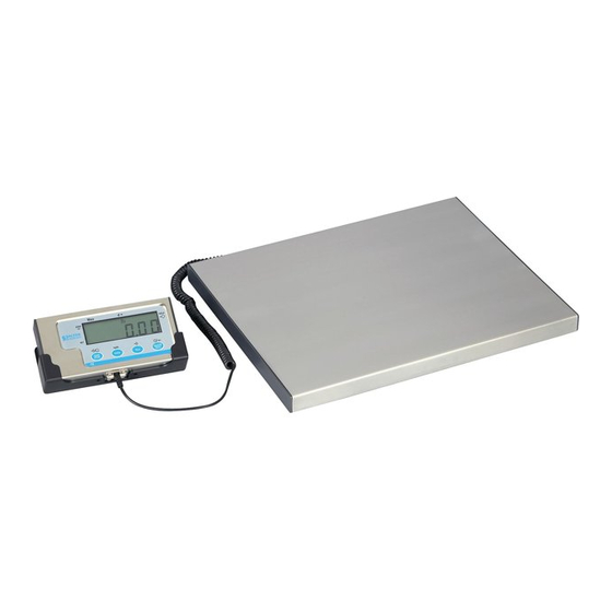
- Page 1 LPS-150 SCALE Operation Manual Contents subject to change without notice Version 1.0 2006-08-10...
- Page 2 Declarations of compliance Wa r n i n g s Electrical installation United States This equipment has been tested and found to comply with the limits for a Class A digital device, pursuant to Part 15 of the FCC Rules. These limits are designed For your protection, all mains (11 0V or 230V) equipment used to provide reasonable protection against harmful interference when the where damp or wet conditions may occur, must be supplied from a...
-
Page 3: Table Of Contents
Operation Manual Thank you for purchasing the 140 indicator. Please read all operating instructions carefully before use and keep the following points in mind: * Avoid lengthy exposure to extreme heat or cold, your scale works best when operated at normal room temperature. Always allow the scale to acclimate to a CONTENT normal room temperature before use * Allow sufficient warm up time. -
Page 4: Ⅱ. Key Function
Ⅱ. standard SCP-01) KEY FUNCTION: 5. Output data: gross weight, net weight, tare weight, indicator displaying weight, weighing unit etc. FACEPLATE: ·OPERATION INTERFACE: 1. Display: 0.65” (17mm) 7-segment LCD, 5 digits 2. Keyboard: 4-key push button ·POWER: 1. Alkaline Batteries: 4 x “AAA” size cells When all displayed segments of LCD flashed, this indicates the batteries are low below 4.9V and you’d better to replace batteries;... - Page 5 to output the data according to P4 setting. Hold these two buttons to show firmware version; A/D code or input working voltage of indicator. UNIT UNIT Choose weighing units among kg-lb-lb: oz Note: The weighing units that can be used are restricted by display division, and calibration weight unit (restricted by P8, P9, and P10): Hold these two buttons to enter setting mode when the sealed calibration For example, if the calibration unit is “kg”;...
-
Page 6: Ⅲ. Calibration
hold down TARE and ON/OFF/ZERO buttons to enter calibration mode. No function When the indicator shows” CAL-?”, the scale is ready for calibration. Press TARE to confirm and go to next step, or press ON/OFF/ZERO to exit the calibration mode. Choose the weight inner code or input working voltage to The 140 indicator will display “CAP.--”, that means the following data is the be displayed. - Page 7 scale’s zero-point. Move away any weight on the scale. Press TARE button the displayed data will blink. If the indicator gets reasonable data, it will to confirm, or press ON/OFF/ZERO to exit this mode. calculate and store all parameters in EEPROM. And then it will auto-reset and When ‘CAL.P1’...
- Page 8 position of the zero-point potentiometer on PCB; however, the software only and UNIT key until ‘SEtUP’ is shown, that means the ON/OFF/ZERO deals with positive value. So, is you are the position of zero-point scale is in SETUP mode. potentiometer is error; adjust potentiometer’s position to make the ADC data 2.
- Page 9 x=3: 9600bps 5.4) P4.x: RS232 mode setting x=4: 19200bps x=0: No RS232 function. It will not transmit or receive any data although the scale is with RS232 hardware. RS232 function can be only 5.6) P6.x: RS232 communication data format activated when scale is in normal weighing mode. x=0: 8N0 8 digits, no odd or even , 1 start bit, 1stop bit x=1:Press PRINT/HOLD key, the scale will output the current stable...
- Page 10 x=0: no decimal (x10 Calibration Display division value in different weight unit that can be used –1 x=1: one decimal digit (x10 division value Lb:oz (oz) –2 x=2: two decimal digits (x10 0.0001lb Not available 0.0001lb Not available –3 x=3: three decimal digits ( x10 0.001 lb 0.0005 kg 0.001 lb...
- Page 11 x=0: the range is set to calibration zero point (CAL.P0) +1%FS 5.15) P15.x: select which zero point will be used when powered on and x=1: the range is set to calibration zero point (CAL.P0) +2%FS weight signal is NOT within the power-on zero-point range: x=2: the range is set to calibration zero point (CAL.P0) +5%FS x=0: Choose current weight as current power-on zero point.
- Page 12 x=6: 120%FS 2.2) The length of the weight field will be 7 digit weight data, one for minus x=7: 150%FS sign, one for decimal point, two for measure unit (e.g. “lb”, “kg”). If the unit x=8: 200%FS is lb:oz, another two for “lb” and one for a space (<sp>) after lb. Units of x=9: No limitation measure abbreviations are always lower case.
- Page 13 all others (8) Command: ④ <LF><p>w1w2w3w4w5w6<dp>w7u1u2<CR><LF>H1H2H3<CR><ETX> Response: Unrecognized command ---Scale is stable, and the current weight unit is kg or lb. With or without decimal <LF>? <CR><ETX> point and the position is as per the P9 setting and current unit. 2.5) Output status bit meaning: ⑤...
- Page 14 1200 0.1200 1.200 12.00 120.0 1200 12000 0.1600 1.600 16.00 160.0 1600 16000 1000 0.2000 2.000 20.00 200.0 2000 20000 1500 0.1500 1.500 15.00 150.0 1500 15000 1200 0.2400 2.400 24.00 240.0 2400 24000 2000 0.2000 2.000 20.00 200.0 2000 20000 1500 0.3000...
-
Page 15: Ⅷ. Meaning Of Some Displayed Symbols
0.3750 3.750 37.50 375.0 3750 37500 --------- ADC is below min. range; _ _ _ 0.4000 4.000 40.00 400.0 4000 40000 ¯ ¯ ¯ ¯ ¯ ---------- weight signal is too large 1000 0.5000 5.000 50.00 500.0 5000 50000 _ _ _ _ _ ------- weight signal is too small 1200 0.6000 6.000... -
Page 16: Ⅹ.key Definition Summary
Ⅹ.Key Definition summary: Normal weighing mode ON/OFF/ (more than 3s) ZERO Enter setup mode MODE DEFINITION UNIT ON/OFF/ Enter or exit HOLD mode; output the Normal weighing mode ZERO Normal weighing mode data as per P4,P5,P6 setting Enter calibration mode when (more than 3s) HOLD Setup mode/Calibration... - Page 17 Resolution select: 500,600,750,800,1000,1200, 1500,2000,2400,2500, 3000, 3500, 4000, 5000, Weight signal within power-on zero point range, 6000, 7000, 7500, 8000, 10000, 12000, 15000, P7.xy 00-31 Choose which data as current power-on zero 20000, 25000, 30000, 35000, 40000, 50000, P14.x 0, 1, 2 point;...
- Page 18 B66 2TE Tel: +44 (0) 870 444 6132 Fa x : +44 (0) 870 010 2241 Email: sales@salterbrecknell.co.uk Web site: www.averyweigh-tronix.com Salter Brecknell Weighing Products USA 1000 Armstrong Drive Fairmont MN 56031 Toll Free: 800-637-0529 Phone: 507-238-8702 Fax: 507-238-8271 Email: sales@salterbrecknell.com...
Need help?
Do you have a question about the LPS-150 and is the answer not in the manual?
Questions and answers