
Summary of Contents for RGBlue MHD-44(AO)
- Page 1 18Gbps 4K@60Hz With Audio De-embedding 4X4 HDMI MATRIX SWITCHER MHD-44(AO) User Manual VER 1.0 Stock Code 873117 en.rgble.com 400-1661-021...
-
Page 2: Table Of Contents
Thank you for purchasing this product For optimum performance and safety, please read these instructions carefully before connecting, operating or adjusting this product. Please keep this manual for future reference. Surge protection device recommended This product contains sensitive electrical components that may be damaged by electrical spikes, surges, electric shock, lighting strikes, etc. -
Page 3: Introduction
4X4 HDMI MATRIX SWITCHER 4K2K@60Hz 18Gbps With Audio De-embedding 1. Introduction This RGBLE MHD-44(AO) high-performance HDMI Matrix Switcher can switch any of these four HDMI 2.0 sources to four HDMI 2.0 displays. Each input and output support up to 4K60 444 resolution and HDCP 2.2. -
Page 4: Package Contents
3. Package Contents Item 4×4 HDMI 2.0 18Gbps Matrix Switcher 12V/2.5A Locking Power Adapter IR Remote Mounting Ears 38KHz IR Receiver Cable (1.5 meters) 3-pin Phoenix Connector User Manual 4. Specifications Technical HDMI Compliance HDMI 2.0 HDCP Compliant HDCP 2.2 and HDCP 1.4 Video Bandwidth 594MHz / 18Gbps 4K2K 50/60Hz 4:4:4... - Page 5 Connection Inputs 4×HDMI Type A [19-pin female] 4×HDMI Type A [19-pin female] Outputs 4×L/R audio out [3.5mm Stereo Mini-jack] 4×COAX audio out [RCA] 1x TCP/IP [RJ45] Control ports 1x RS-232[3-pin phoenix connector] 1x IR EXT [3.5mm Stereo Mini-jack] General Housing Metal Enclosure Color Black...
-
Page 6: Operation Controls And Functions
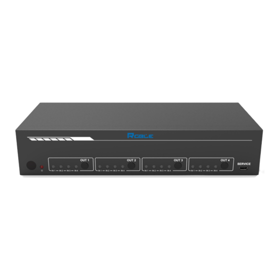
5. Operation Controls and Functions 5.1 Front Panel Name Function Description IR Sensor IR input for remote control of the switcher. Power LED Red LED indicates that the unit is powered. Green LED indicates when the input is selected for IN 1 IN2 / IN3 / IN4 LED respective output. -
Page 7: Connecting To The Switcher
5.3 Connecting to the Switcher 1) Connect the desired HDMI input sources. 2) Connect the desired HDMI display devices. 3) Connect any CONTROL inputs that may be required: TCP/IP, RS-232 or IR IN. 4) Connect any audio devices to either the Coaxial or L/R outputs. 5) Connect the 12V DC PSU. -
Page 8: Using The Built-In Web Gui Interface
7. Using the Built-In Web GUI Interface The Switcher has a built-in Web interface to provide a means of controlling or configuring various settings. There are six pages available, each of which will be outlined in detail in the following sections: The six pages are: 1. - Page 9 Step 3: Enter the Switcher’s IP address into your browser on the PC to enter Web GUI page. After entering the IP address the following log in screen will appear: Select the Username from the list and enter the password. The default passwords are: Username User Admin...
- Page 10 ■ Video page The Video page allows selection of the inputs source and set the presets. To this preset setting, first you need to select the desired input source to four output ports. Then click the Save button to save the setting. When you click the line Set button, this preset you have saved will be used.
- Page 11 4K2K60Hz_444 Stereo Audio 2.0 4K2K60Hz_444 Dolby/DTS 5.1 4K2K60Hz_444 HD Audio 7.1 4K2K60Hz_444 Stereo Audio 2.0 HDR 4K2K60Hz_444 Dolby/DTS 5.1 HDR 4K2K60Hz_444 HD Audio 7.1 HDR USER_1 USER_2 COPY_FROM_TX_1 COPY_FROM_TX_2 COPY_FROM_TX_3 COPY_FROM_TX_4 This page also provides a means of sending a binary EDID file to either User 1 or User 2 EDID memories: 1.
- Page 12 ■ System page The system page allows setting of the panel lock and beep on/off, control RS-232 port baud rate. This page is also used to install new firmware update, restore the factory default settings and reboot the Switcher. Stock Code 873117 en.rgble.com 400-1661-021...
-
Page 13: Api Control Command
8. API control command The Switcher can also be controlled by RS-232. Connect a PC by using a serial cable and open any of a Serial Command tool on the PC such as Comm Operator, Docklight or Hercules, etc. to send command for controlling the Switcher. Please see the following connection diagram. Figure 1: 3-pin phoenix connector to USB Important: 1. - Page 14 Power power on/off the device,z=0~1(z=0 power s power z! power on off, z=1 power on) r power! get current power state power on /power off Reboot... s reboot! reboot the device System Initializing... Initialization Finished! SYSTEM Setup help! Lists all commands r type! Get device model MHD-44(AO)
- Page 15 Set the serial port baud rate of RS02 s baud rate module, Baudrate:115200 xxx! z=(115200,57600,38400,19200,9600,4800) r baud Get the serial port baud rate of RS02 Baudrate:115200 rate! module Set the control ID of the product, s id z! id 888 z=000~999 Output Setting Set input x to output y,x=1~4,...
- Page 16 IN1 EDID: 4K2K60_444, Stereo Audio 2.0 IN2 EDID: 4K2K60_444, Get EDID status of the input x, x=0~4(0=all Stereo Audio 2.0 r edid in x! inputs) IN3 EDID: 4K2K60_444, Stereo Audio 2.0 IN4 EDID: 4K2K60_444, Stereo Audio 2.0 r edid data Get the EDID data of the hdmi output y port, EDID: 00 FF FF FF FF FF FF hdmi y...
- Page 17 Get network MAC r mac addr! Mac address: 00:1C: 91:03:80:01 address Set network IP Set IP mode: Static. mode to static IP or s ip mode z! Please use "s net reboot!" command or repower device DHCP, z=0~1 (z=0 to apply new config! Static, z=1 HDCP) Get network IP r ip mode!
-
Page 18: Connection Diagram
9. Connection Diagram Stock Code 873117 en.rgble.com 400-1661-021...
Need help?
Do you have a question about the MHD-44(AO) and is the answer not in the manual?
Questions and answers