Advertisement
Quick Links
Advertisement

Subscribe to Our Youtube Channel
Related Manuals for KMW MINT 5 P

Summary of Contents for KMW MINT 5 P
- Page 1 Operator Manual cum Parts Catalogue for KMW – MIN T 5 PETROL...
-
Page 2: Table Of Contents
We are providing three labor free Services within six month of purchase, requested to utilize our services according to the service maintenance schedule mentioned in the operator manual. This Manual Cover’s all variants of MINT 5 P Power Weeder. Please refer relevant details only applicable for your Machine. - Page 3 1. MINT 5 P Warranty Period and Warranty Policy Guide Lines 1.1 Warranty Period Sl. No. Product Warranty Coverage Machine ( Engine, 6 months or 250 operational hours whichever is earlier from Transmission) Date of Sale to First Purchaser Proprietary parts, Like:...
-
Page 4: Technical Specifications -Mint 5 P
1.3 WARRANTY REGISTRATION CARD / Sales Intimation Card MINT 5P Details Model Invoice No. Invoice Date Engine No. Frame No. Warranty Start Date Warranty End Date 1) Forest Professionals 2) Orchard 3) Vegetable Crops Use of MINT 4) Hill Area 5) House Garden Customer Details Name... - Page 5 Weight 65 kgs 3. Safety Precautions Do’s and Don’ts 3.1 Safety Precautions of MINT 5 P 1. Read and follow the owner’s manual and safety instructions carefully before operating. 2. Don’t allow children to use the machine. 3. In general all moving parts particular shafts & blades shall be treated as dangerous 3.2 DOs...
- Page 6 Be adequately trained on MINT 5 P and when required; c) Obtain and read the operator’s manual before using the MINT 5 P for the first time; and when required. d) Wear suitable non slip footwear, suitable hearing protection and comfortable clothing.
- Page 7 35. Never run the engine in a closed garage or confined area. 3.4 Recognize Decals Information’s An important safety incorporated into MINT 5 P is the warning and information decals found in various parts of the machine. Control & Equipment...
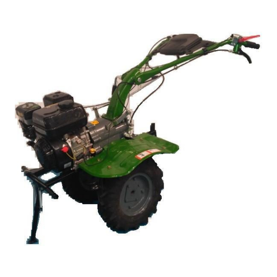
- Page 8 ACCELERATOR RESISTANCE BAR CLUTCH LEVER TRANSMISSION OIL FILLER CAP FORWARD LEVER PROTECTING FENDER REVERSE LEVER TOOL BOX HANDLEBAR HEIGHT ADJUSTER FRONT STAND...
-
Page 9: Operating Instruction
5. Operating Instruction 5.1 Engine Controls Fuel Valve Lever The fuel valve opens and closes the passage between the fuel tank and the carburettor. The fuel valve lever must in the ON position for the engine to run. When the engine is not in use, leave the fuel valve lever in the OFF position to prevent carburettor flooding and to reduce them possibility of the... - Page 10 5.2 Starting The Engine 1. Move the fuel valve lever to the ON position. 2. To start a cold engine, move the choke lever to the CLOSE position. To restart a warm engine, leave the choke lever in the OPEN position.
- Page 11 5.3 Stopping the Engine To stop the engine in an emergency, simply turn the engine switch to the OFF position. Under normal conditions, use the following procedure. 1. Move the throttle lever to the SLOW position. 2. Turn the engine switch to the OFF position. 3.
- Page 12 5.5 Transmission controls Accelerator (Throttle) Control Lever The throttle lever controls the engine speed and tine rotations. Moving the throttle lever in the direction shown, run the engine faster or slower. To increase engine RPM, pull the lever to anti clockwise direction. To decrease engine RPM, push the lever to clockwise direction.
- Page 13 Resistance Bar Resistance Bar controls tilling depth and should always be used when tilling. It enables you to compensate for the hardness of the soil. Ideal resistance bar height will depend on the type of soil being tilled and soil conditions at the time of tilling.
- Page 14 6.3 Safety Precautions Make sure the engine is off before you begin any maintenance or repairs. This will eliminate several potential hazards such as: Carbon monoxide poisoning from engine exhaust. Be sure there is adequate ventilation whenever you operate the engine. ...
- Page 15 6.6 Maintenance Chart Free Service Period Frequency (from date of delivery) Each 1st Month Each Month Every Month Every year/ Item / 20 hrs. / 50 hrs. / 100 hrs. 300 hrs. Clean Crank Case CLEAN INSPECT LEVEL Engine Oil CHANGE Valve Clearance CHECK-ADJUST...
- Page 16 6.7 Assembly of Engine 6.7.1 Assembly of Piston and Connecting Rod 6.7.2 Assembly of Crankcase...
- Page 17 6.7.3 Assembly of Cylinder Head and Valve Assembly 6.7.4 Assembly of Cylinder Head 6.7.5 Assembly of Governor...
- Page 18 6.8 Refueling CCP196 fuel tank capacity: 3.5 Liters With the engine stopped, remove the fuel tank cap and check the fuel level. Refill the tank if the fuel level is low. Refuel in a well-ventilated area before starting the engine. If the engine has been running, allow it cool. Refuel carefully to avoid spilling fuel.
- Page 19 6.10 Engine Oil Level Check Check the engine oil level with the engine stopped and in a level position. 1. Remove the filler cap/dipstick and wipe it clean. 2. Insert and remove the dipstick without screwing it into the filler neck. Check the oil level shown on the dipstick. 3.
- Page 20 6.12 Servicing Your Engine Engine Oil Recommendations Oil is a major factor affecting performance and service life. Use 4- stroke automotive detergent oil. SAE 10W-30 is recommended for general use. Other viscosities shown in the chart may be used when the average temperature in your area is within the recommended range.
- Page 21 5. Fill the air cleaner case to the OIL LEVEL mark with the same oil that is recommended for the engine. Oil- Bath type Air Filter Oil capacity: 60 ml 6. Reassemble the air cleaner, and tighten the wing nut securely.
- Page 22 6.17 Idle Speed Adjustment 1. Start the engine outdoors, and allow it to warm up to operating temperature. 2. Move the throttle lever to its slowest position. 3. Turn the throttle stop screw to obtain the standard idle speed. 6.18 Spark Arrester Service Your engine is factory-equipped with spark CCP196...
- Page 23 6.21 Engine Oil Storage Precautions 1. Change the engine oil. 2. Remove the spark plugs 3. Pour a tablespoon (5-10 cc) of clean engine oil into the cylinder. 4. Pull the starter rope several times to distribute the oil in the cylinder. 5.
-
Page 24: Troubleshooting
6.23 Lubrication Specification Chart USE ONLY KOEL RECOMMENDED OIL & LUBICANTS Model Lubricants Type Specifications Quantity Replacement Engine Oil KOEL CARE – PETRO PLUS 0.6 LTRS. Every Service MIN T 5 Transmission Oil SAE 80W - 90, GI-4 1.3 LTRS. 200 Hrs or 5 months Air Cleaner SAE 20W - 90, GI-4... - Page 25 Engine Stalls (Stops Running) Sr. No. Cause Action Taken Low Oil Level Check the quantity of oil, replenish if insufficient. Black Smoke from Engine Cause Action Taken Drain fuel from tank, filter and fuel pipes, Flush fuel system and Adulterated Fuel in tank refill with petrol.
-
Page 26: Wiring Diagrams
7.3 GEAR BOX TROUBLESHOOTING Reverse Gear not in position Sr. No. Cause Action Taken Reverse Cable wire failure Readjust or change the cable wire Reverse gear shaft loose Tighten the bolt at end of reverse gear shaft Reverse gear fork jammed Clear the gap of reverse gear fork axle and the steel sleeve Sleeve is over worn Change the sleeve... -
Page 27: Parts Catalogue
9. Parts Catalogue 9.1 Power Weeder CCP196 Petrol Engine Catalogue SL.NO DESCRIPSION GROUP CODE CRANKCASE ASSEMBLY AP5.001... CRANKCASE COVER ASSEMBLY AP5.002... CYLINDER HEAD AND CYLINDER HEAD COVER AP5.003... ASSEMBLY FLYWHEEL ASSEMBLY AP5.004... CAMSHAFT ASSEMBLY AP5.005... CRANKSHAFT ASSEMBLY AP5.006... RECOIL STARTER ASSEMBLY AP5.007... - Page 28 CRANKCASE ASSEMBLY PART NUMBER DESCRIPTION AP5.001.01.0.PR CRANKCASE AP1.001.20.0.PR OIL LEVEL SWITCH ASSEMBLY AP1.001.06.0.00 GOVERNOR GEAR AP1.001.11.0.PR SLIDING SLEEVE AP1.001.12.0 PR REGULATING SWAY BAR 6&8 AP1.001.19.0.00 DRAIN PLUG SCREW M10X15X1.25 WITH WASHER AP1.001.09.0.PR SLIDING SLEEVE WASHER AP1.001.14.0.PR CLIP AP1.001.17.0.PR BEARING 6205 AP1.001.18.0.PR OIL SEAL 25X41.25X6 AP1.001.03.0.00 ORING AP1.001.05.0.PR NUT M10X1.5...
- Page 29 CYLINDER HEAD & COVER ASSEMBLY SL. NO. PART NUMBER DESCRIPTION AP5.003.02.0.PR VALVE GUIDE (EXHAUST) AP5.003.03.0.PR VALVE GUIDE (INLET) AP5.003.01.0.PR CYLINDER HEAD AP5.003.04.0.PR VALVE GUIDE LOCK AP5.003.05.0.PR CYLINDER HEAD GASKET AP5.003.06.0.PR CYLINDER HEAD COVER AP5.003.07.0.PR CYLINDER HEAD COVER GASKET AP5.003.08.0.PR BREATHER TUBE AP5.003.09.0.PR BOLT (M6X12) AP5.003.11.0.PR...
- Page 30 CRANKCASE COVER ASSEMBLY SL. NO. PART NUMBER DESCRIPTION AP1.002.01.0.PR CRANK CASE COVER AP1.002.02.0.00 FRONT OIL SEAL 25X41.25X6 AP1.001.17.0.PR BEARING 6205 AP1.002.04.0.PR CRANCASE COVER GASKET 5&6 AP1.002.06.0.PR DIPSTICK WITH SEAL AP5.002.03.0.PR DOWEL PIN 10 X 16 CC3.001.042.0.00 FLANGE BOLT M8X1.25X35 L 8.8 CRANKSHAFT ASSEMBLY (SPLINE TYPE) SL.
- Page 31 CAMSHAFT ASSEMBLY SL. NO. PART NUMBER DESCRIPTION AP1.005.15.0.PR CAMSHAFT AP5.005.08.0.00 EXTENSION SPRING AP1.005.07.0.00 VALVE LIFTER AP5.005.06.0.00 PUSH ROD PISTON & CONNECTING ROD ASSEMBLY SL. NO. PART NUMBER DESCRIPTION AP5.013.02.0.PR PISTON RING SET AP5.013.01.0.PR PISTON AP1.013.02.0.PR PISTON PIN AP1.013.03.0.PR PISTON PIN CIRCLIP AP1.013.40.0.00 CONNECTING RODASSEMBLY AP1.013.08.0.PR...
- Page 32 CARBURETOR ASSEMBLY SL. NO. PART NUMBER DESCRIPTION AP5.014.01.0.PR O RING ID10 OD13 –1.5MM AP5.014.02.0.PR FLANGE BOLT FOR CHAMBER (M8x1.0x7) AP5.014.03.0.PR WASHER ID6 OD10—0.6MM AP5.014.04.0.PR RING FOR FLOAT CHAMBER 47x2 AP5.014.05.0.PR FLOAT CHAMBER AP5.014.06.0.PR FLOAT AP5.014.07.0.PR AP5.014.08.0.PR MAIN JET AP5.014.09.0.PR IMMERSION TUBE AP5.014.11.0.PR SCREW THROTTLE ADJUSTMENT AP1.014.14.0.00...
- Page 33 RECOIL STARTER ASSEMBLY SL. NO. PART NUMBER DESCRIPTION AP5.007.20.0.PR RECOIL STARTER ASSEMBLY AP1.007.08.0.PR RECOIL STARTER KNOB AP1.007.07.0.PR RECOIL STARTER CASE AP1.007.06.0.PR STARTING ROLLER AP1.007.04.0.PR RATCHET AP1.007.12.0.PR WASHER AP1.007.02.0.PR SPRING COVER AP1.007.03.0.PR FRICTION SPRING FOR RECOIL STARTER AP1.007.11.0.00 SPIRAL SPRING AP1.007.05.0.PR SPRING RETURN N11.051.06.0.00 FLANGED SCREW - M6 X 1.0 X 12 MM AP1.007.09.0.00 RECOIL STARTER ROPE N11.051.09.0.00 FLANGED SCREW - M6 X 1.0 X 8 MM...
- Page 34 REGULATING CONTROL SYSTEM PART NUMBER DESCRIPTION AP5.015.10.0.PR CONTROL SYSTEM ASSEMBLY REGULATING ARM AP1.015.15.0.PR FLANGED SCREW - M6 X 1.0 X 20 MM AP1.015.03.0.PR FLANGE NUT M6 AP1.015.06.0.PR PULLING ROD AP1.015.04.0.PR FINE REGULATING SPRING AP1.015.05.0.PR BACK SPRING AP5.015.09.0.PR SPRING - REGULATING ARM CONNECTING AP5.015.14.0.PR FLANGED SCREW M5 X 15 AP5.015.13.0.PR...
- Page 35 AIR CLEANER ASSEMBLY SL. NO. PART NUMBER DESCRIPTION AP5.008.01.0.PR O RING AP5.008.02.0.PR DOWEL AP5.008.03.0.PR DOWEL AP5.008.04.0.PR AIR CLEANER (TOP CASE) AP5.008.05.0.PR AIR CLEANER (LOWER CASE) AP5.008.06.0.PR AIR CLEANER ELEMENT AP5.008.07.0.PR ROUND CASE AP5.008.08.0.PR PLASTIC COVER AP5.008.09.0.PR ROUND WASHER FOR TOP CASE AP5.008.11.0.PR WING NUT N11.051.02.0.00...
- Page 36 MUFFLER ASSEMBLY SL. NO. PART NUMBER DESCRIPTION AP5.016.10.0.PR MUFFLER ASSEMBLY AP5.016.01.0.PR MUFFLER AP5.016.02.0.PR MUFFLER COVER AP5.016.03.0.PR MUFFLER CAP AP5.016.04.0.PR SCREW AP5.016.05.0.PR HEX NUT M8 AP5.016.07.0.PR SPARK ARRESTER AP5.016.08.0.PR SCREW AP5.016.09.0.PR SCREW AP5.016.11.0.PR GASKET FOR MUFFLER...
- Page 37 FANCASE AND AIR HOOD SL. NO. PART NUMBER DESCRIPTION AP5.017.01.0.PR REGULATING CONTROL SYSTEM AP5.017.02.0.PR SPRING AP5.017.03.0.PR BOLT ADJUSTING SCREW AP5.017.04.0.PR FLANGE BOLT M6X12 AP5.017.05.0.PR AIR HOOD AP5.017.06.0.PR SIDE COVER PLATE WITH BRACKET AP5.017.07.0.PR OIL SAFEGUARD SWITCH AP5.017.08.0.PR ON/OFF SWITCH AP5.017.09.0.PR CLIP AP5.017.11.0.PR FLANGE BOLT M6X20...
- Page 38 FUEL TANK ASSEMBLY SL. NO. PART NUMBER DESCRIPTION AP5.018.01.0.PR FUEL TANK AP5.018.02.0.PR BOLT M6X30 AP5.018.03.0.PR WASHER (RUBBER) AP5.018.04.0.PR FUEL NIPPLE AP5.018.05.0.PR FUEL HOSE CLIP AP5.018.06.0.PR FUEL HOSE AP5.018.07.0.PR FLANGE NUT M6 AP5.018.08.0.PR FUEL TANK CAP WITH GASKET AP5.018.09.0.PR FUEL TANK CAP GASKET AP5.018.11.0.PR FUEL STRAINER...
- Page 39 9.2 POWER WEEDER MINT 5 PETROL TRANSMISSION CATALOGUE Sr. No. Description WHEEL ASSEMBLY CLUTCH ASSEMBLY MAIN SHAFT ASSEMBLY REVERSE SHAFT ASSEMBLY GEAR BOX ASSEMBLY DRY LAND BLADE ASSEMBLY TRANSMISSION BOX ASSEMBLY HANDLE ASSEMBLY AND CONTROLS HANDLE ASSEMBLY...
- Page 40 WHEEL ASSEMBLY SR.NO. PART NO. DESCRIPTION QTY. 57.006.10.000 NUT - M10 X 1.5 57.505.10.000 SPRING WASHER - M10 57.507.10.0.00 PLAIN PUNCHED WASHER - M10 P05.P002.021.0.00 AXLE ASSEMBLY P08.0002.051.0.00 RIGHT RIM DIA 400 P08.0002.052.0.00 INNER TUBE DIA 400 P08.0002.153.0.00 TYRE DIA 400 P08.0002.054.0.00 LEFT RIM DIA 400 57.003.10.025...
- Page 41 MAIN SHAFT ASSEMBLY SR. NO. PART NO. DESCRIPTION QTY. P05.P004.001.0.00 MAIN SHAFT P05.P004.002.0.00 STEEL RETAINING RING 50.529.05.000 STEEL BALL DIA 6 P05.P004.051.0.00 MAIN SHAFT SPRING P05.P004.003.0.00 MAIN SHAFT DOUBLE GEAR REVERSE SHAFT ASSEMBLY SR.NO. PART NO. DESCRIPTION QTY. 50.001.03.032 SPLIT PIN DIA 2.5 X 32 50.050.12.000 CASTLE NUT M12 57.507.12.000...
- Page 42 GEAR BOX ASSEMBLY SR.NO PART NO DESCRIPSION 57.006.10.000 HEX NUT M10 57.507.10.000 SPRING WASHER M10 57.505.10.000 PLAIN WASHER M10 P05.P007.021.0.00 SHIFT GEAR ARM P05.P007.058.0.00 SHIFTING GEAR FORK SLEEVE P05.P007.051.0.00 O TYPE SEAL RING DIA 11.2 X 1.8 P05.P007.002.0.00 SHIFTING FORK SHAFT ASSEMBLY P05.P007.003.0.00 SHIFTING BLOCK P05.P007.004.0.00...
- Page 43 P05.P007.022.0.00 MAINSHAFT PROTECTION COVER 57.002.06.020 HEX BOLT M6 X 20 P05.P007.024.0.00 COUNTER GLAND P05.P007.025.0.00 COUNTER GLAND GASKET P05.P007.026.0.00 THRUST NUT DIA 16 P05.P007.059.0.00 TAPERED ROLLER BEARING 30203 57.002.10.025 HEX BOLT M10 X 25 57.507.10.000 SPRING WASHER M10 57.507.12.000 PLAIN WASHER M10 P05.P007.028.0.00 CLUTCH FORK SHAFT SLEEVE P05.P007.052.0.00...
- Page 44 TRANSMISSION BOX ASSEMBLY SR.NO PART NO. DESCRIPSION 50.001.03.032 SPLIT PIN DIA 2.5 X 32 50.050.12.000 CASTLE NUT M12 57.505.12.000 SPRING WASHER M12 57.507.12.000 PLAIN WASHER M10 P05.P009.003.0.00 DRIVEN BEVEL GEAR P08.0009.051.0.00 TAPERED ROLLER BEARING 30206 P05.P009.001.0.00 TRANSMISSION BOX P05.P009.055.0.00 DEEP GROOVE BEARING 6305 P05.P009.106.0.00 WEAR-RESISTANT MAT P05.P009.005.0.00 OUTPUT SHAFT SLEEVE P05.P009.007.0.00 TRANSMISSION BEVEL GEAR...
- Page 45 HANDLE ASSEMBLY AND CONTROLS...
- Page 46 SL.NO PART NO DESCRIPSION QTY. P05.P010.053.0.00 ACCELERATOR ASSEMBLY P05.P010.021.0.00 HANDLE ASSEMBLY P05.P010.064.0.00 PLASTIC SLEEVE P05.P010.026.0.00 REVERSE LEVER P05.P010.051.0.00 EMERGENCY STOP LEVER P05.P010.067.0.00 CLUTCH LEVER P05.P010.022.0.00 LEVER GEAR SHIFTING P05.P010.052.0.00 TOOL BOX 57.002.16.150 HEX BOLT M16 X 150 57.507.16.000 PLAIN WASHER M16 57.505.16.000 SPRING WASHER M16 P05.P010.122.0.00...
- Page 47 GROUPCODE TRANSMISSION BOX ASSEMBLY 57.002.10.040 HEX BOLT M10 X 40 P05.P010.042.0.00 WELDING TRAILER BODY ASSEMBLY P05.P010.005.0.00 GEAR BOX SEALING GASKET P05.P008.054.0.00 DRY LAND BLADES RIGHT P05.P010.043.0.00 FRONT SUPPORT BRACKET RIGHT 57.002.10.040 HEX BOLT M10 X 40 P05.P006.044.0.00 ENGINE SUPPORT PLATE P05.P006.021.0.00 BUMPER ASSEMBLY 57.006.06.000...
- Page 48 HANDLE BAR ASSEMBLY SR.NO. PART NO DESCRIPSION 50.001.03.025 SPLIT PIN DIA 2.5 X 25 57.507.12.000 PLAIN WASHER M12 P05.P010.022.0.00 LEVER GEAR SHIFTING P05.P010.052.0.00 TOOL BOX P05.P010.123.0.00 PLASTIC SLEEVE, GEAR LEVER SHIFTER P05.P010.053.0.00 ACCELERATOR ASSEMBLY P05.P010.119.0.00 PIN SHAFT DIA 7 X 22 P05.P010.121.0.00 PIN SHAFT DIA 10 X 22 P05.P010.059.0.00 CLUTCH CABLE P05.P010.021.0.00 HANDLE ASSEMBLY...
-
Page 49: Service Coupons And Check List
10. Service Coupons & Check List Coupon No. : FREE SERVICE COUPON 1st Free Service (50 hrs. or 1 month) (50 hrs. or 1 month from Date of Sale whichever is earlier) Date of Service : Model : Date of Sale : Chassis No. - Page 50 Check List For 1 st Free Service Mark √after each operation is Mark √after each operation is completed Mark Mark completed Clean Weeder thoroughly Check abnormal noise and vibration Clean crank case after running the engine for 5- Check all control lever function 10 minutes, clean oil screen assembly.
-
Page 51: Pdi Check List
11. PDI check list PDI CHECK LIST Sr. No. Engine Mark Check Engine Oil and Top up to Recommended Level Check Fuel Tank And fuel lines for leakage & tighten if required Check air cleaner oil and Top up to the mark Check Engine foundation bolts and tighten, if necessary Crank the engine 3 - 4 times Check exhaust condition...
Need help?
Do you have a question about the MINT 5 P and is the answer not in the manual?
Questions and answers