
Summary of Contents for CAENels DAMC-FMC2ZUP
- Page 1 DAMC-FMC2ZUP User’s Manual DAMC-FMC2ZUP Zynq Ultrascale+ MPSoC based Dual FMC/FMC+ Carrier Board with MicroTCA.4 D1.1 support User’s Manual All Rights Reserved © CAEN ELS s.r.l. Rev. 1.0 – April 2021...
- Page 2 DAMC-FMC2ZUP User’s Manual This product is licensed by CAEN ELS s.r.l. in AREA Science Park S.S. 14 km 163,5 – 34149 Basovizza (TS) Italy Mail: info@caenels.com Web: www.caenels.com...
-
Page 3: Table Of Contents
DAMC-FMC2ZUP D ..............6 ESCRIPTION DAMC-FMC2ZUP F ............... 7 EATURES ..................9 RDERING OPTIONS DAMC-FMC2ZUP C ..........10 OMPONENTS VERVIEW DAMC-FMC2ZUP ARCHITECTURE ............12 ..............12 UNCTIONAL LOCK IAGRAM ................ 18 LOCK RCHITECTURE ..............20 OWER UPPLY RCHITECTURE JTAG C .................... - Page 4 DAMC-FMC2ZUP User’s Manual Document Revisions Document Revision Date Comment Preliminary Release October, 2020 Preliminary Release April, 2021 First Release...
- Page 5 DAMC-FMC2ZUP User’s Manual Safety Information The following table shows the general environmental requirements for a correct operation of referred board in this User’s Manual: Environmental Conditions Requirements Environment Indoor use Operating Temperature 0°C to 50°C Operating Humidity 20% to 80% RH (non-condensing)
-
Page 6: Introduction
FMC2ZUP FMC carrier board. 1.1 DAMC-FMC2ZUP Description The DAMC-FMC2ZUP is a high-end FMC/FMC+ carrier in MicroTCA.4 form factor based on the new family of ZYNQ Ultrascale+ MPSoCs. The host FPGA is the Xilinx ZU11EG-L2 or the ZU19EG-L2. The PS (Processing System) section offers a quad-core ARM Cortex-A53 operating up to 1.333 GHz, a dual core ARM-R5 real-... -
Page 7: Damc-Fmc2Zup Features
The Zynq Ultrascale+ family of FPGAs is supported by all modern development tools, such as Vivado, HLS, Yocto, Petalinux, SDSoC and SDAccel, this makes DAMC-FMC2ZUP capable of addressing the ever-growing need of processing power while also reducing development time. 1.2 DAMC-FMC2ZUP Features •... - Page 8 DAMC-FMC2ZUP User’s Manual Introduction Transceivers low-power) routed to FMC HPC, backplane, Front Panel, Zone3 etc. 4 GTR Transceivers (6.0 Gbps) routed to SATA Transceivers links and FMC connector • FPGA core voltage can be set to low-power (0.72V) or standard power (0.85V) operation via MMC user commands, this allows to switch between...
-
Page 9: Ordering Options
DAMC-FMC2ZUP User’s Manual Introduction 1.3 Ordering options There are two ordering option for the two versions of the DAMC-FMC2ZUP carrier board: Description Ordering Code MicroTCA.4 Zynq UltraScale+ FMC+ Carrier DAMCFMC2ZUP1 with XCZU11EG-L2FFVC1760E MicroTCA.4 Zynq UltraScale+ FMC+ Carrier DAMCFMC2ZUP2 with XCZU19EG-L2FFVC1760E... -
Page 10: Damc-Fmc2Zup Components Overview
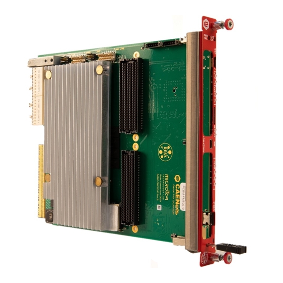
4. Secondary FPGA Spartan 7 5. DDR4 memory modules, PS (a), PL (b) 6. Power Section 7. Ethernet IC 8. Main JTAG Connector 9. FPGA PS - ARM JTAG for PS Connector 10. Extension Power Connectors Figure 1-1: DAMC-FMC2ZUP - Top side... - Page 11 DAMC-FMC2ZUP User’s Manual Introduction Components on side #2 (bottom-side): 1. MMC 2. MLVDS transceivers 3. Flash memories for FPGA configuration: a. Zynq Ultrascale+ b. Spartan 7 4. Power Management 5. Clock Section 6. eMMC memory Figure 1-2: DAMC-FMC2ZUP - Bottom side...
-
Page 12: Damc-Fmc2Zup Architecture
DAMC-FMC2ZUP User’s Manual DAMC-FMC2ZUP Architecture 2. DAMC-FMC2ZUP Architecture This chapter offers a technical overview of the many features implemented on this board. 2.1 Functional Block Diagram This section presents the block diagram of the connectivity implemented on the board, excluding the clock network which is described in the next section. In the following paragraphs are described the connections with the backplane, with FMC/FMC+ connectors and with Zone3. - Page 13 DAMC-FMC2ZUP User’s Manual DAMC-FMC2ZUP Architecture PCIe over Fat Pipe (ports 4 to 7): PCIe x4 Gen.3 (Gen.4 can be enabled but is not officially supported) connectivity is achieved using the Hard IP blocks located in the PL area of the FPGA.
- Page 14 DAMC-FMC2ZUP User’s Manual DAMC-FMC2ZUP Architecture Figure 2-1: Block Diagram...
- Page 15 DAMC-FMC2ZUP User’s Manual DAMC-FMC2ZUP Architecture 2.1.2 FMC+ (VITA 57.4) The following interconnections are available over the FMC+ connector: • LA (00-33) LVDS Differential pairs: All the LA signals of the FMC interface are routed to the PL section of the FPGA.
- Page 16 DAMC-FMC2ZUP User’s Manual DAMC-FMC2ZUP Architecture 2.1.3 FMC HPC (VITA 57.1) The following interconnections are available over the FMC connector: • LA (00-33) LVDS Differential pairs: All the LA signals of the FMC interface are routed to the PL section of the FPGA.
- Page 17 DAMC-FMC2ZUP User’s Manual DAMC-FMC2ZUP Architecture 2.1.4 Zone3 Connectivity Zone3 connectivity in accordance to recommended pinout of Class D1.1 is achieved as follows: • Fixed LVDS outputs OUT0 to OUT2: These links use specialized LVCMOS to LVDS drivers under full control of MMC Stamp SoM (System on Module).
-
Page 18: Clock Tree Architecture
DAMC-FMC2ZUP User’s Manual DAMC-FMC2ZUP Architecture 2.2 Clock Tree Architecture The clock architecture is based on a bidirectional cross-point switch and 3 independent PLLs. The cross-point switch is connected to: • 4 Telecommunication Clock signals (TCLKA, TCLKB, TCLKC and TCLKD) provided on standard MicroTCA backplanes •... - Page 19 DAMC-FMC2ZUP User’s Manual DAMC-FMC2ZUP Architecture Figure 2-2: Clock Network Diagram...
-
Page 20: Power Supply Architecture
DAMC-FMC2ZUP User’s Manual DAMC-FMC2ZUP Architecture 2.3 Power Supply Architecture The power supply section is implemented by a cascade of DC/DC converters and LDOs, all of which are controlled by a PMBus manager IC, this ensures that the proper sequencing, as required by the FPGA and IC specifications, is maintained both at start-up and power-down. -
Page 21: Jtag Chain
DAMC-FMC2ZUP User’s Manual DAMC-FMC2ZUP Architecture 2.4 JTAG Chain The board implements two, not fully independent, JTAG chains. The main JTAG chain can be accessed through the P1 Connector (see Figure 1-1 for location on board) or the MicroTCA backplane and is "mediated" by the MMC Stamp SoM. The MMC Stamp is responsible to select and/or insert more devices into the JTAG chain. -
Page 22: Flash Programming
The firmware needed to operate the White Rabbit End point on the DAMC- FMC2ZUP can be derived from the OpenHardware Cute-WR project (information available on ohwr.org). The firmware customization required will later on be made available under the OpenHardware license terms. Figure 2-6: Block Diagram of DAMC-FMC2ZUP WhiteRabbit Section... -
Page 23: Module Management Controller
DAMC-FMC2ZUP User’s Manual Module Management Controller 3. Module Management Controller The MMC Stamp SoM implements standard MicroTCA module management as well as the following additional features: • JTAG multiplexing • HPM update • Boot mode selection for both ZUP and Spartan-7 FPGAs •... -
Page 24: Hpm Update
DAMC-FMC2ZUP User’s Manual Module Management Controller 3.3 HPM update The MMC Stamp currently supports in-application-update of its firmware using the PICMG HPM.1 standard. Upcoming MMC firmware releases will also be able to update FPGA images. The firmware upgrade can be done with ipmitool using a command like this: ipmitool -H <mch_address>... -
Page 25: Auto-Detection Of Variable Fmc Voltage (Vadj)
DAMC-FMC2ZUP User’s Manual Module Management Controller 3.7 Auto-detection of variable FMC voltage (Vadj) The VCC_Vadj power rail towards the FMC slots can be adjusted within the limits allowed for the ZUP’s I/Os. The MMC supports detection of the FMC module’s supported voltage range (by reading out the DCLoad FRU record of the Vadj channel) and automatic setting of a suitable level for Vadj. -
Page 26: Front Panel Available Features
DAMC-FMC2ZUP User’s Manual Front Panel Available Features 4. Front Panel Available Features The board provides many features accessible from the front panel, as shown in the following figure: Section Description USB Type-C connector: USB2, USB3 and DisplayPort are available on... -
Page 27: Microusb Front-Panel Connector
DAMC-FMC2ZUP User’s Manual Front Panel Available Features 4.1 microUSB Front-panel Connector The microUSB front panel connector allows access to: • MMC Stamp and • Main FPGA PS consoles from an external PC. On Windows™ systems, when an USB cable is connected to this interface, 2 new COM peripherals will be detected. -
Page 28: Appendix
5.1 Extension Power Connectors The following figure defines the pin assignment of the 2 Extension Power Connectors available on the board (see Figure 1-1: DAMC-FMC2ZUP - Top side) Figure 5-1: Pin allocation of Extension Power Connectors Pins 1, 3 and 5 are connected to VCC12_FMC, a 12V power rail available whenever the FMC power is enabled on the regular connectors. -
Page 29: High Density Microhdmi Type-D
DAMC-FMC2ZUP User’s Manual Appendix 5.2 High Density microHDMI type-D On the front panel it is also present a High Density microHDMI connector (type- D) that can be used for trigger/clock/white-rabbit purposes. The block diagram of the available connections is shown in the following figure:... - Page 30 DAMC-FMC2ZUP User’s Manual Appendix The microHDMI pin connections of connector are listed in the following table: Name Pin # Type TRIGGER_1_N LVDS 2V5 INOUT TRIGGER_1_P LVDS 2V5 INOUT TRIGGER_0_P LVDS 2V5 INOUT PASSIVE TRIGGER_0_N LVDS 2V5 INOUT SFP_TX_P PASSIVE SFP_TX_N...
- Page 31 DAMC-FMC2ZUP User’s Manual Appendix 3V3 is connected to the board local 3.3V supply rail and can be used to power an external SFP/SFP+ module. The pin assignments are listed in the following table: Name Component Pin # Bank Notes Voltage...
-
Page 32: Mmc Commands
DAMC-FMC2ZUP User’s Manual Appendix 5.3 MMC commands The list of available MMC commands is shown in the following figure: Command Arguments Description ? / h / help Show list of available commands Clear screen Reset MMC Show firmware version [0..n]... - Page 33 DAMC-FMC2ZUP User’s Manual Appendix Figure 5-6: FMC connections...
- Page 34 DAMC-FMC2ZUP User’s Manual Appendix Figure 5-7: FMC+ connections...
Need help?
Do you have a question about the DAMC-FMC2ZUP and is the answer not in the manual?
Questions and answers