
Subscribe to Our Youtube Channel
Related Manuals for HTP Micro Cut 380

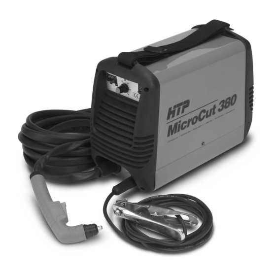
Summary of Contents for HTP Micro Cut 380
- Page 1 America Inc. HTP Air Plasma Cutting System Micro Cut 380 HTP America, Inc. 3200 Nordic Road Arlington Heights, IL 60005-4729 • • 1-800-USA-WELD 847-357-0700 FAX: 847-357-0744 www.usaweld.com • • •...
-
Page 2: Table Of Contents
Micro Cut 380 Parts Breakdown ........ -
Page 3: Warranty
Limited Warranty In the case of HTP's breach of warranty or any other duty with Subject to the terms and conditions hereof, HTP warrants to its respect to the quality of any goods, the exclusive remedies Distributor/Dealer that all new and unused Equipment furnished... - Page 4 b. Hot sparks or hot metals can fall into cracks in floors or wall Equipment Maintenance: Faulty or improperly maintained openings and cause a hidden smoldering fire. Make certain plasma cutting equipment results in poor cut-quality. It can that such openings are protected from hot sparks and metal. cause physical injury or death through fires or electrical shock.
-
Page 5: Inspection
Install the bracket with 2 Phillips head screws to the back of your Micro Cut 380 as shown in Fig 2. Install the regulator in the quick connect fitting and secure it to the bracket. Install a _ male quick disconnect fitting to match your air supply. -
Page 6: Electrical Connection
DISCONNECT SWITCH. (Fig 3) Ground Clamp Assembly Your Micro Cut 380 has been designed to operate from 220 volt single phase power wired for a minimum of 16 amps. The green or yellow-green wire must be connected to ground. The blue and brown wires must be connected to the hot legs of the 220-volt power. -
Page 7: Operation
1) ON-OFF SWITCH – the On-Off switch is located on the 6) RED "GENERAL ALARM" LIGHT – this lamp will rear of your Micro Cut 380. I is on and O is off. When the illuminate red when the duty cycle of the machine has been switch is in the on position, it will light up. -
Page 8: Maintenance And Service
(Fig. 6) Piercing 6. If any damage to the machine or torch is noticed, contact your local distributor or HTP America, Inc. directly at 8. Familiarize yourself with the consumable parts and their 1-800-USA-WELD. correct assembly onto the torch head (see page 10). -
Page 9: Cutting Tips
1. When making long, straight cuts, it may be easier to use a metal straight edge as a guide. Simply clamp it to the workpiece to be cut. HTP America, Inc. also manufactures a complete Circle-Cutting and Straight-Line Traversing Assembly for frequent cutting of circles and lines. - Page 10 Spare Parts List Ref# Description Part# Ref# Description Part# Potentiometer 112017 Belt 322408 Resistor 112048 Frame 322497 Rectifier 112357 Front Panel 482829 Relay 112898 Back Panel 482830 114028 Diaphram 482833 Gas Regulator 120203 Side Member 482834 Air Switch 122144 Pressure Guage 602072 Solenoid Valve 122155...
-
Page 11: Micro Cut 380 Parts Breakdown
Micro Cut 380 Torch Parts Breakdown Ref # Description Part # Trigger Switch 14009 Electrodes 38003 Extended Electrodes 62003E Swirl Ring 62058 Cutting Tips 38030 Extended Cutting Tip 62030E Gas Diffuser 38005 Handle 38008 Torch Head 38002 Complete Torch 38180... -
Page 12: Wiring Diagram
MicroCut 380 Wiring Diagram...
Need help?
Do you have a question about the Micro Cut 380 and is the answer not in the manual?
Questions and answers