Table of Contents
Advertisement
Advertisement
Table of Contents

Related Manuals for Emheater EM15-SP Series


Summary of Contents for Emheater EM15-SP Series
- Page 2 Due to the continuous improvement of solar inverter, this document will be updated without prior notice. EM15-SP series solar inverter complies with the following international standards. All products have passed the CE certification.
- Page 3 Contents 1. Safety Information and Precautions ......................... 1 1.1 Safety Information ............................1 2. Product Information ..............................3 2.1 Designation Rules ............................3 2.2 Model and Technical Data ..........................3 2.3 Product Appearance and Installation Dimension ................... 4 2.3.1 Product Appearance ..........................4 2.3.2 Appearance and Installing Dimension ....................
- Page 4 Warning: Indicates that failure to comply with the notice will result in personal injury or property damage. Read this manual carefully so that you have a thorough understanding. Installation, commissioning or maintenance may be performed in conjunction with this chapter. EMHEATER will assume no liability or responsibility for any injury or loss caused by improper operation.
- Page 5 1. Safety Information and Precautions EM15-SP User Manual Warning: ⚫ When two solar inverters are laid in the same cabinet, arrange the installation positions properly to ensure the enough cooling effect. ⚫ Do not drop wire residue or screw into the solar inverter. Failure to comply will result in damage to the solar inverter.
- Page 6 EM15-SP User Manual 2. Product Information 2. Product Information 2.1 Designation Rules EM15 Series Frequency Inverter Products Type: PV use Voltage range: 1: DC 250~400V to Three phase AC 220V 3: DC 350~750V to Three phase AC 380V Adaptable motor: 7d5: 7.5KW ;011: 11KW Diagram 2-1 Designation rules 2.2 Model and Technical Data Table 2-1EM15-SP Model and technical data...
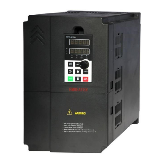
- Page 7 2. Product Information EM15-SP User Manual 2.3 Product Appearance and Installation Dimension 2.3.1 Product Appearance Diagram 2-2 Product appearance (With potentiometer) 2.3.2 Appearance and Installing Dimension Diagram 2-3 Appearance and installation dimension of EM15 series (Plastic housing structure) Appearance and installing dimension ( Unit: mm ) Matching inverter Voltege Power Range...
- Page 8 EM15-SP User Manual 2. Product Information Diagram 2-4 Appearance and installation dimension of EM15 series (Metal housing structure) Appearance and installing dimension ( Unit: mm ) Matching inverter Voltege Power Range 3PH 220V 15~18.5kW Φ7 3PH 380V 30~37kW 3PH 220V 22kW Φ10 3PH 380V...
- Page 9 3. Installation of Frequency Inverter EM15-SP User Manual 3.Installation of Frequency Inverter 3.1 Installation Environment 1. The place with indoor vents or ventilation devices. 2. The environment temperature shall be -10℃~40℃. If the temperature is over 40℃but less than 50℃, better to take down the cover of frequency inverter or open the front door of cabinet to facilitate heat dissipation.
- Page 10 EM15-SP User Manual 3. Installation of Frequency Inverter 3.3 Sketch and Description of Main Circuit Terminals 3.3.1 Function and Description of Main Circuit Terminals Three phase 220V output:EM15-SP1-d75~EM15-SP1-011 Three phase 380V output:EM15-SP3-d75~EM15-SP3-022 Three phase 380V output:EM15-SP3-030~EM15-SP3-090 Three phase 380V output:EM15-SP3-110~EM15-SP3-400 Terminal symbol Function description R, S, T...
- Page 11 3. Installation of Frequency Inverter EM15-SP User Manual 3.4 Control Circuit and Main Circuit Terminals Description 3.4.1 Control Circuit and Main Circuit Wiring Diagram3-2 EM15-SP control circuit and main circuit wiring 3.4.2 Control Circuit Terminal Layout Diagram3-3 EM15-SP control circuit terminal sketch diagram 3.4.3 Description of Control Circuit Terminals Terminal Type...
- Page 12 EM15-SP User Manual 3. Installation of Frequency Inverter Terminal Type Terminal Name Terminal function description Symbol External power supply input It connect with +24V default terminals AI1-GND Analog input 1 1. Input range: DC 0V~10V/ 0mA~20mA(decided by jumper Analog AI1/AI2 on the control board); AI3: DC -10V~+10V AI2-GND Analog input 2 input...
- Page 13 3. Installation of Frequency Inverter EM15-SP User Manual 3.5 Collection Diagram For Different Motor Photovoltaic cell Note: For the EM15-SP1S series, U and V as single Phase 220V output terminal. EM15-SP + - U V W Water Tank Water Pipe C o n t r o l Te r m i n a l Pump Diagram3-4 220V three phase installed without water level sensor (PV Input)
- Page 14 EM15-SP User Manual 3. Installation of Frequency Inverter 3.5.1 The Wiring of Water-Level Automatic Control The wiring for floater water-level switch connected by cable The common port, which using floate water-level switch connected by cable, is fed to the terminal “COM” of EM15-SP.
- Page 15 3. Installation of Frequency Inverter EM15-SP User Manual Remarks: When the actual water-level in the reservoir is lower than horizontal line of low water-level, DI4 and DI5 will be disconnected from the COM as well as controller automatically strat the pum. On the contrary, if the actual water-level is higher than the horizontal line of high water-level, DI4 and DI5 will be connected to COM as well as controller automatically stop the pump to prevent water overflow.
- Page 16 EM15-SP User Manual 4. Operation and Display 4 Operation and Display 4.1 Instruction of Operation and Display Diagram 4-1 Operating panel Name Function The 5-digit LED display is able to display the set frequency, output frequency, monitoring LED display area data and fault codes.
- Page 17 4. Operation and Display EM15-SP User Manual 4.2 Function Code Table Debugging specification: 1. Set A1-00 to turn on photovoltaic mode, or it’ll run in ordinary inverter mode; Set A1-01 to enable MPPT function to search Vmpp voltage automatically; Otherwise, the default Vmpp voltage needs to be set manually; 2.
- Page 18 EM15-SP User Manual 4. Operation and Display Code Parameter Name Functional description Default Property ★ A1-23 Low light sleep delay 0~30000s ★ A1-24 Light weak wake-up time 0~30000s ★ A1-25 Underload detection current 0.00~300.00A 0.00A ★ A1-26 Underload detection time 0~30000s ★...
- Page 19 4. Operation and Display EM15-SP User Manual Code Parameter Name Functional description Default Property Unit's digit: Frequency source selection. 0: Main frequency source X 1: X and Y calculation (calculation result determined by ten's digit) 2: Switchover between X and Y 3: Switchover between X and "X and Y calculation"...
- Page 20 EM15-SP User Manual 4. Operation and Display Code Parameter Name Functional description Default Property (b0-13) Frequency upper limit ☆ b0-16 0.00 Hz~ maximum frequency(b0-13) 0.00 Hz offset ☆ b0-17 Frequency lower limit 0.00 Hz ~frequency upper limit(b0-15) 0.00 Hz 0: Forward direction ☆...
- Page 21 4. Operation and Display EM15-SP User Manual frequency of stopping DC braking waiting time of ★ b1-09 0.0s~100.0s 0.0s stopping DC braking current of ★ b1-10 0%~100% stopping DC braking time of ★ b1-11 0.0s~100.0s 0.0s stopping Group b2: Auxiliary Function Code Parameter Name Functional description...
- Page 22 EM15-SP User Manual 4. Operation and Display threshold Action after running time 0: Continue to run ☆ b2-22 reached 1: Stop 0: Fan working during running ☆ b2-23 Cooling fan control 1: Fan working during power on ☆ b2-24 Dormant frequency 0.00Hz ~wakeup frequency (b2-26) 0.00Hz ☆...
- Page 23 4. Operation and Display EM15-SP User Manual 15: Frequency source switchover 16: Switchover between main frequency source X and digital setting frequency 17: Switchover between auxiliary frequency source Y and digital setting frequency 18:Terminal 1 for Command source switchover 19: Terminal 2 for Command source switchover 20: Speed control/Torque control switchover 21: Torque control prohibited 22: PID pause...
- Page 24 EM15-SP User Manual 4. Operation and Display ☆ b3-23 DI5 ON delay time 0.0s~3000.0s 0.0s ☆ b3-24 DI5 OFF delay time 0.0s~3000.0s 0.0s Unit's digit: DI1 valid mode. 0: High level valid 1: Low level valid Ten's digit: DI2 valid mode. 0, 1 (same as DI1) ★...
- Page 25 4. Operation and Display EM15-SP User Manual 34: AI1 input exceeded limitation 35: Alarm output (all faults) 36: Present running time reached 37: Accumulative power-on time reached 38: Accumulative running time reached ☆ b4-10 FMR ON delay time 0.0s~3000.0s 0.0s ☆...
- Page 26 EM15-SP User Manual 4. Operation and Display detection delay time ☆ b4-35 Any current reaching 1 0.0%~100.0% (rated motor current) 100.0% amplitude of any current ☆ b4-36 0.0%~100.0% (rated motor current) 0.0% reaching 1 ☆ b4-37 Any current reaching 2 0.0%~100.0% (rated motor current) 100.0% Amplitude of any current...
- Page 27 4. Operation and Display EM15-SP User Manual Corresponding setting of AI ☆ b5-25 curve 4 inflection point 1 -100.0%~+100.0% 30.0% input Corresponding setting of AI ☆ b5-26 curve 4 inflection point 2 b5-23~b5-27 6.00V input AI curve 4 inflection point ☆...
- Page 28 EM15-SP User Manual 4. Operation and Display Group b6: Pulse/Analog Output Terminals Code Parameter Name Functional description Default Property 0: Running frequency corresponding to 0~Max. operation frequency 1: Set frequency corresponding to 0~Max. operation ☆ frequency b6-00 FMP function selection 2: Output current corresponding to 0~Doubled motor rated current 3: Output torque (absolute value) corresponding to...
- Page 29 4. Operation and Display EM15-SP User Manual Bit03: Output voltage (V) Bit04: Output current (A) Bit05: Output power (kW) Bit06: Output torque (%) Bit07: DI input status Bit08: DO output status Bit09: AI1 voltage (V) Bit10: AI2 voltage (V) Bit11: AI3 voltage (V) Bit12: Count value Bit13: Length value Bit14: Load speed display...
- Page 30 EM15-SP User Manual 4. Operation and Display 3: 3 decimal display ● b9-07 Heatsink temperature 0.0° C ~100.0° C ● b9-08 Accumulative running time 0~65535 h Accumulative power-on ● b9-09 0~65535 h time Auxiliary display ● b9-11 Corresponding U0 group parameters 00004 parameters Group bA: Communication Parameters...
- Page 31 4. Operation and Display EM15-SP User Manual Motor overload protection ☆ bb-02 0.20~10.00 1.00 gain Motor overload ☆ bb-03 50%~100% pre-warning coefficient ☆ bb-09 Fault auto reset times 0~20(Unlimited number of times) Relay action selection 0: Not act bb-10 ☆ during fault auto reset 1: Act Time interval of fault auto...
- Page 32 EM15-SP User Manual 4. Operation and Display Unit's digit: Motor overload, Err11. 0: Free stop 1: Stop according to the stop mode 2: Continue to run Ten's digit: Power input phase loss, Err12. Fault protection action Same as unit's digit ☆...
- Page 33 4. Operation and Display EM15-SP User Manual Backup frequency of ☆ bb-38 0.0%~100.0% (maximum frequency) 100.0% abnormality Inverter overload protection bb-39 85%-115% 100% gain Group bC: Fault Diagnosis Code Parameter Name Functional description Default Property – – ● bC-00 First fault type –...
- Page 34 EM15-SP User Manual 4. Operation and Display Overcurrent alarm delay ☆ bd-01 0.0~600s 0.00 time Group C0: PID Control Function Code Parameter Name Functional description Default Property 0: C0-01 1: AI1 2: AI2 3: AI3 ☆ C0-00 PID setting source 4: Pulse setting (HDI) 5: Communication setting 6: Multi-function...
- Page 35 4. Operation and Display EM15-SP User Manual Frequency upper limit of ☆ C0-18 0.00 ~ maximum frequency 0.00 Hz PID reverse rotation ☆ C0-19 PID deviation limit 0.0%~100.0% 0.0% ☆ C0-20 PID differential limit 0.00%~100.00% 0.10% Maximum positive ☆ C0-21 deviation between two PID 0.00%~100.00% 1.00%...
- Page 36 EM15-SP User Manual 4. Operation and Display cycle 2: Repeat after the frequency inverter runs one cycle Unit's digit: Record of power failure. 0: no record after power off Simple PLC record 1: record after power off ☆ C2-01 selection Ten's digit: Record of stopping.
- Page 37 4. Operation and Display EM15-SP User Manual PLC Segment 8 Acceleration/deceleration ☆ C2-19 time of simple PLC Segment 8 Running time of simple ☆ C2-20 0.0s(h)~6553.5s(h) 0.0s (h) PLC Segment 9 Acceleration/deceleration ☆ C2-21 time of simple PLC Segment 9 Running time of simple ☆...
- Page 38 EM15-SP User Manual 4. Operation and Display 0.0~100%( Corresponding pressure Sleep wakeup pressure ☆ C3-04 percentage) (Mpa) ☆ C3-07 Sleep frequency 0.00~maximum frequency 20.00HZ The lasting time of ☆ 0~250s C3-08 frequency is less than sleep pressure 0:frequency sleep available ☆...
- Page 39 4. Operation and Display EM15-SP User Manual 0.0s: No action ★ d0-29 Encoder fault detection time 0.0s 0.1s~10.0s 0: No auto-tuning 1: Asynchronous motor static auto-tuning ★ d0-30 Motor auto-tuning selection 2: Asynchronous motor dynamic complete auto-tuning 3: Asynchronous motor static complete auto-tuning Group d1: Vector Control Parameters Code Parameter Name...
- Page 40 EM15-SP User Manual 4. Operation and Display 4: Pulse setting (HDI) 5: Communication setting 6: MIN (AI1, AI2) 7: MAX (AI1, AI2) Full range of values 1~7 corresponds to the digital setting of d1-27. Torque digital setting in ☆ d1-26 -200.0%~200.0% 150.0% torque control...
- Page 41 4. Operation and Display EM15-SP User Manual 2: AI2 3: AI3 4: Pulse setting (HDI) 5: Multi-function 6: Simple PLC 7: PID 8: Communication setting (Note: 100.0% corresponds to the rated motor voltage) Voltage digital setting for ☆ d2-14 0 V ~ rated motor voltage V/F separation 0.0s~1000.0s Voltage rise time of V/F...
- Page 42 EM15-SP User Manual 4. Operation and Display ● U0-14 Load speed display 0~65535 0~65535 ● U0-15 PID setting 0~65535 ● U0-16 PID feedback ● U0-17 PLC stage ● U0-18 Input pulse frequency 0.00kHz ~100.00 kHz -3000.0Hz~3000.0 Hz Feedback speed, ● U0-19 -300.00Hz~300.00 Hz unit:0.01Hz...
- Page 43 4. Operation and Display EM15-SP User Manual state ● 0~99 U0-62 Current fault code Sent value of point-point ● -100.00%~100.00% U0-63 communication ● 0~63 U0-64 Number of slaves ● -200.00%~ 200.00% U0-65 Torque upper limit Group A0: System Parameters Code Parameter Name Functional description Default...
- Page 44 EM15-SP User Manual 4. Operation and Display ☆ A2-15 Torque compensation gain 80~150 Rotational speed tracking ☆ 0~1000 A2-16 closed loop current KP Rotational speed tracking ☆ 0~1000 A2-17 closed loop current KI Rotational speed tracking Model ☆ 30%~200% A2-18 closed loop current limit dependent Rotational speed tracking...
- Page 45 5. Fault Diagnosis and solution EM15-SP User Manual 5. Fault Diagnosis and Solution 5.1 Fault Alarm and Countermeasures EM15-SP inverter has 35 types of warning information and protection function. In case of abnormal fault, the protection function will be invoked, the inverter will stop output, and the faulty relay contact of the inverter will start, and the fault code will be displayed on the display panel of the inverter.
- Page 46 EM15-SP User Manual 5. Fault Diagnosis and solution The input voltage is not within the allowable range. Adjust the input voltage to the allowable range. Fault Code Err09 Fault Type Low voltage 1: Instantaneous power failure occurs on the input 1: Reset the fault.
- Page 47 Appendix I. Modbus Communication Protocol EM15-SP User Manual Appendix I. Modbus Communication Protocol EM15series of inverter provides RS485 communication interface, and adopts MODBUS communication protocol. User can carry out centralized monitoring through PC/PLC to get operating requirements. And user can set the running command, modify or read the function codes, the working state or fault information of frequency inverter by Modbus communication protocol.
- Page 48 EM15-SP User Manual Appendix I. Modbus Communication Protocol the single master “Inquiry/Command”, all of slaves will return a signal that is a response; for the broadcast information provided by master, slave needs not feedback a response to master machine. Communication data structure Modbus protocol communication data format of EM15 series inverter is shown as following.
- Page 49 Appendix I. Modbus Communication Protocol EM15-SP User Manual 1Byte 2Byte >3.5Byte 1Byte 1Byte Slave reads and Target Read the Free response error station command Error type correction and Free (Start frame) frame address (0x83) L……H Calculate CRC Error types: correction 01-Command code error 02-Address error 1Byte...
- Page 50 EM15-SP User Manual Appendix I. Modbus Communication Protocol When the CRC is appended to the message, the low-order byte is appended first, followed by the high-order byte. unsigned int crc_chk_value(unsigned char *data_value,unsigned char length unsigned int crc_value=0xFFFF; int i; while(length--) crc_value^=*data_value++;...
- Page 51 Appendix I. Modbus Communication Protocol EM15-SP User Manual 1006H Output torque 1016H Voltage before AI1correction 1007H Running speed 1017H Voltage before AI2correction 1008H DI input terminal 1018H Voltage before AI3correction 1009H DO output terminal 1019H Linear speed 100AH AI1 voltage 101AH Present power-on time 100BH...
- Page 52 EM15-SP User Manual Appendix I. Modbus Communication Protocol Analog output AO2 control: (write in only) Command word address Command function 2003H 0~7FFF indicates 0%~100% Pulse output control: (write in only) Command word address Command function 2004H 0~7FFF indicates 0%~100% Inverter fault description: Inverter fault Inverter fault information description...
- Page 53 Appendix I. Modbus Communication Protocol EM15-SP User Manual baud ratio of the host computer and the inverter should be consistent. Otherwise, the communication is impossible. The higher the baud ratio is, the faster the communication is. Modbus Data format Default No check, data format <8,N,2>...
Need help?
Do you have a question about the EM15-SP Series and is the answer not in the manual?
Questions and answers