Advertisement
Quick Links
PROFI- 2510 / PROFI-2541(SC)
Introduction
This user guide introduces the user how to implement the PROFI-2510
/ PROFI-2541(SC) into their applications in a quick and easy way.
Therefore, it only provides the basic instructions. For more detail
information about the PROFI-2510 / PROFI-2541(SC) module, please refer
to the PROFI-2510 / PROFI-2541(SC) user manual in the ICP DAS product
CD or download it from ICP DAS web site.
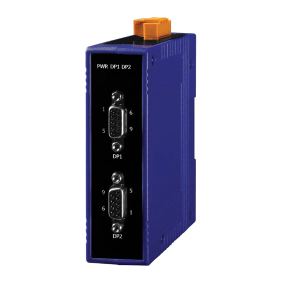
PROFIBUS Connector
The PROFIBUS connector is a standard 9-pin D-Sub connector, there are
only 4 pins used in PROFI-2510 / PROFI-2541(SC). The pins VP and GND
support the 5 volt power to active terminal resistor, and the A-Line and
B-Line is the data bus.
Status Indicator
PROFI-2510
It provides three status indicator, In PROFI-2510, they are PWR LED
(red),DP1 LED(green) and DP2 LED (green). In PROFI-2541(SC), they are
PWR LED (red), TxD LED(green) and RxD LED (green). When the power is
Quick Start User Guide
Pin No.
Signal
3
B-Line
5
GND
6
VP
8
A-Line
Meaning
Receive/Transmit data – plus
Power ground of active terminator
Power 5 volt of active terminator
Receive/Transmit data - minus
PROFI-2541(SC)
Advertisement

Summary of Contents for Profibus PROFI-2510
- Page 1 Receive/Transmit data - minus The PROFIBUS connector is a standard 9-pin D-Sub connector, there are only 4 pins used in PROFI-2510 / PROFI-2541(SC). The pins VP and GND support the 5 volt power to active terminal resistor, and the A-Line and B-Line is the data bus.
- Page 2 Terminating Resistors In order to minimize the reflection effect of the signal transmission, PROFIBUS device has to fit with an active terminal resistor at both first node and last node. The connection of active terminating resistors is shown in above circuit diagram. The PROFI-2510 / PROFI-2541(SC) doesn’t have any terminating resistors inside.
- Page 3 Switch Wire Connection PROFI-2510 If PROFI-2510 is a end device of PROFIBUS segment 1 and PROFIBUS segment 2. The terminal resistor of segment 1 is ON. The terminal resistor of segment 2 is ON. If PROFI-2510 is an intermediary device of PROFIBUS segment 1. The...
- Page 4 PROFI-2541(SC)
Need help?
Do you have a question about the PROFI-2510 and is the answer not in the manual?
Questions and answers